Recommended articles:
-

-
Global Energy Interconnection
Volume 8, Issue 5, Oct 2025, Pages 804-820
A review on high-frequency electromagnetic interference induced by power electronics in new electric power systems☆
Abstract
Abstract New electric power systems characterized by a high proportion of renewable energy and power electronics equipment face significant challenges due to high-frequency (HF) electromagnetic interference from the high-speed switching of power converters.To address this situation, this paper offers an in-depth review of HF interference problems and challenges originating from power electronic devices.First, the root cause of HF electromagnetic interference, i.e., the resonant response of the parasitic parameters of the system to highspeed switching transients, is analyzed, and various scenarios of HF interference in power systems are highlighted.Next, the types of HF interference are summarized, with a focus on common-mode interference in grounding systems.This paper thoroughly reviews and compares various suppression methods for conducted HF interference.Finally,the challenges involved and suggestions for addressing emerging HF interference problems from the perspective of both power electronics equipment and power systems are discussed.This review aims to offer a structured understanding of HF interference problems and their suppression techniques for researchers and practitioners.
0 Introduction
Global energy demand is rising, and the power grid,currently the primary source of carbon emissions, plays a crucial part in the achievement of carbon peak and carbon neutrality goals.The core objective of constructing new power systems is to prioritize clean and low-carbon energy.Accelerating energy structure transformation and advancing low-carbon development are critical objectives for new power systems.The usage share of new energy sources, which are heavily reliant on power electronics equipment,is steadily rising.Additionally,digital technology is increasingly being used to monitor the operating statuses of such systems to ensure reliable operation [1].
Electric power electronization and digitization are defining features of new power systems.Wind and solar power, as forms of renewable energy, are inherently intermittent and unstable, requiring extensive use of power electronics equipment for energy conversion and control.Power electronics equipment,characterized by high energy conversion efficiency and precise control,is widely utilized across various components of new power systems, including generation, grid, load, and storage [2].Additionally,new power systems demand advanced digitization.Digital sensing and Internet of things technologies enable comprehensive monitoring and connection of diverse terminal devices, making it possible to observe, measure, and control the resources involved in generation, grid, load, and storage.This improves the ability of new power systems for comprehensive perception, intelligent interaction, and flexible adjustment [3].
In contrast to traditional power systems, modern systems are experiencing a steady rise in their proportion of power electronic and digital equipment [4].Power electronic converters meet consumer demands by providing precise and rapid control of electrical energy, significantly boosting both performance and efficiency.The high prevalence of power electronics equipment alters the form and operational characteristics of power systems.Owing to the significant presence of power electronic devices, contemporary research is chiefly concerned with challenges related to the stability of operations and the quality of power in modern electrical systems [5,6].Although power electronics equipment enhances energy conversion effi-ciency, the ongoing integration of power electronics and digital technologies in new power systems presents a significant challenge: high-frequency (HF) electromagnetic interference[7].Modern power systems extensively employ various electronic devices and intelligent control systems,which operate over frequencies ranging from several kilohertz to several gigahertz[8,9].HF interference signals can manifest in various forms, including transient pulses, continuous waves, and modulated signals.For instance, the operation of switching devices may generate transient current pulses, whereas inverters may produce modulated waveform interference during conversion processes.The phase and polarization states of interference signals can change across different operational environments and conditions, adding to their complexity and making it more challenging to characterize interference sources.
As HF signals propagate within power systems, they may reflect and refract along different paths,creating multiple propagation paths[10].The signal received at the terminal can thus be a superposition of multiple signals,making it difficult to distinguish interference sources.The broadband and multimodal characteristics of interference make its identification and suppression challenging.Tracing and precisely mitigating interference require not only advanced technological measures but also comprehensive consideration of various factors during the design phase.
HF electromagnetic interference is inherently linked to the rapid switching of power converters under the standard operational conditions of power electronic devices,which are typically within a frequency range of up to 100 MHz.The research thus far has addressed mainly the stability and power quality challenges arising from the integration of power electronics equipment, typically in the low- to medium-frequency ranges.To date, and to the best of the authors’ knowledge, no systematic review of HF electromagnetic interference in new power systems has ever been published.This paper provides an extensive review of HF interference problems and challenges due to power electronic devices in modern power systems,addressing the mechanisms and types of, and suppression methods against, HF interference.
This paper is structured as follows.Section 2 introduces the emerging problem of HF electromagnetic interference in new power systems, analyzing the intrinsic characteristics of power electronics equipment and the root causes of HF interference.Section 3 categorizes the types of HF electromagnetic interference and summarizes existing suppression methods.Finally, Section 4 compares and analyzes different suppression methods and discusses challenges and future work.
1 HF electromagnetic interference in new power systems
1.1 HF electromagnetic interference caused by power electronics equipment
Electronification is a defining characteristic of new electric power systems.Power electronics achieve energy transformation and control through the high-speed switching of semiconductor devices,providing advantages in both highefficiency conversion and precise regulation.The integration of power electronics equipment in new power systems,including in generation, network, load, and storage, has been steadily increasing.As shown in Fig.1, highproportioned new energy and distributed generation(DG)on the source side is controlled by power electronics[11], whereas high-voltage direct current (HVDC) transmission on the grid side is managed by power electronic converters [12,13].Meanwhile, electric vehicles, LED lights, variable-frequency speed-regulating motors, and other new power electronic loads are prevalent on the load side.Energy storage systems use power electronic converters for charging and discharging [14].Power electronics equipment offers high energy-conversion efficiency, but its high-speed switching inevitably generates HF electromagnetic interference in various modes [15].On the other hand, to enhance the comprehensive sensing capability of new power systems,numerous sensors and monitoring terminals are deployed for state sensing, including temperature, magnetic field, and partial discharge (PD) monitoring.However, the HF interference induced by power electronics would threaten the reliability of condition monitoring devices in the power grid.
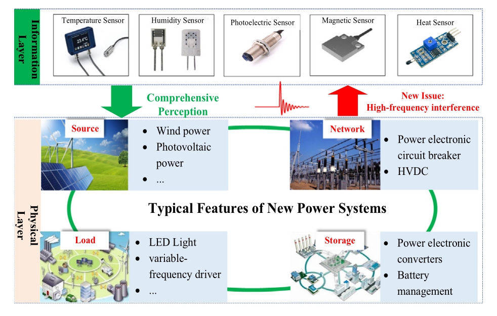
Fig.1.Typical features of new electric power systems.
Power electronic converters address the demands of new power systems by enabling precise and rapid control of electrical energy, resulting in notable enhancements in performance and efficiency.Power electronic devices exhibit multi-time-scale and multi-frequency features during normal operation, as illustrated in Fig.2.Typical frequency components include fundamental harmonics,pulse width modulation(PWM)ripple, and HF electromagnetic oscillation.Most power electronic devices operate at fundamental frequencies typically ranging from tens to hundreds of Hz.Power electronics typically employ PWM techniques,which generate PWM harmonics at the switching frequency and its harmonics.The complex coupling of high-proportion power electronics equipment in fundamental and PWM frequency bands in power systems may lead to problems with stability,e.g.,broadband oscillation, and power quality [16,17].During switching transients, as illustrated in Fig.3, high dv/dt and di/dt excitations are caused by the rapid switching of power devices in power electronics,leading to strong HF electromagnetic oscillations through the coupling of the HF parasitic parameters of the system.These oscillations, with frequencies ranging from tens to 100 MHz, result in electromagnetic interference.HF electromagnetic interference can damage sensitive components in power equipment,leading to equipment failure.This damage is often due to instantaneous voltage spikes and increased temperatures caused by HF signals,which affect the insulation performance and thermal stability of equipment [18,19].HF interference can trigger sudden changes in current,accelerating the aging of components or causing permanent damage [20,21].Such interference adversely impacts the dynamic response of power systems,increasing oscillations and instability.In systems using feedback control,interference can increase signal noise, which reduces phase margins and gain margins and makes the system more susceptible to oscillations and transient instability.
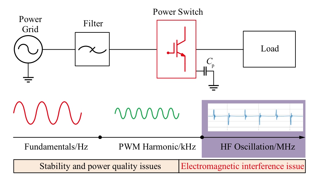
Fig.2.Multi-frequency and multi-time-scale characteristics of power electronics equipment.
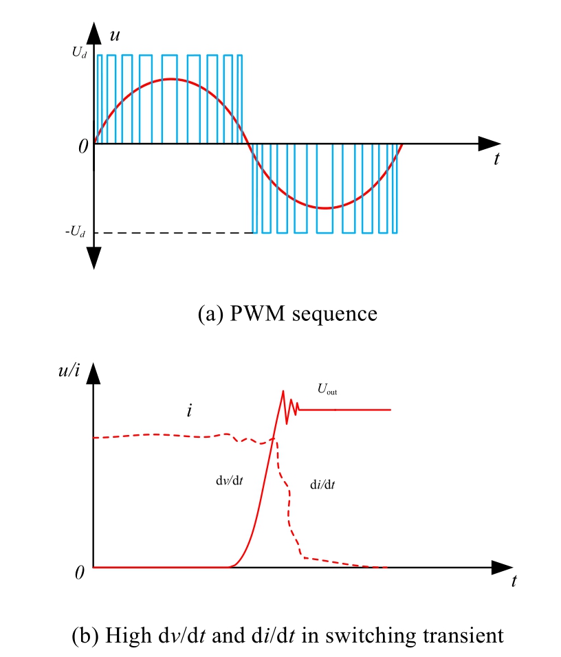
Fig.3.Principle of switching-mode power electronic converters.
In an incident involving a 500-kV tunnel in Shanghai,the cable online monitoring system issued an anomaly alert, indicating a potential fault or abnormal condition.The system is designed to immediately notify relevant personnel when it detects abnormal parameters, such as abnormal temperature, current, or other factors, within the cable tunnel.However, during the on-site inspection,the personnel found no noticeable faults in the tunnel;all equipment and cables appeared to be functioning normally.After a detailed investigation,it was confirmed that the alert was a false alarm.Experts analyzed the incident and suggested that the false alarm was likely due to inaccuracies in data transmission caused by electromagnetic interference from power electronics equipment within the tunnel.This type of interference is particularly common in signal transmission within cable tunnels, highlighting the importance of ensuring accurate data transmission in environments prone to electromagnetic interference.
The root causes of HF electromagnetic oscillation are switching excitation and HF parasitic coupling,which will be analyzed in detail as follows.
1.2 Mechanism of HF switching oscillation
The fundamental cause of HF oscillation is the interaction between the rapid switching of power devices and the HF parasitic parameters present in the system.When power devices switch rapidly, the parasitic inductance and capacitance in the circuit form a resonant circuit.This resonant circuit is excited by the swift switching actions of the power devices, leading to the emergence of oscillation phenomena [22].The amplitude of these oscillations is influenced primarily by two factors:the excitation imposed by the switching action and the inherent HF parasitic characteristics of the system.Rapid switching induces steep changes in current and voltage, which exert greater stress on the parasitic inductance and capacitance, resulting in more pronounced oscillations.The dominant frequency of these oscillations is determined by the resonant parameters of the system, particularly the combination of parasitic inductance and capacitance.These parameters form a resonant circuit with a specific resonant frequency, typically calculated using the formula![]() where L represents the parasitic inductance and C the parasitic capacitance.
where L represents the parasitic inductance and C the parasitic capacitance.
The schematic of a buck converter is shown in Fig.4,where Q represents a silicon carbide (SiC) metal-oxide-s emiconductor field-effect transistor (MOSFET) and D denotes a power diode [23].The components Lo, Co, and RL correspond to the inductor,output capacitor,and load resistor,respectively.On the other hand,Uin,UDS,and Ug represent the input DC supply voltage, MOSFET drainsource voltage, and gate voltage, respectively, whereas the variable iL denotes the inductor current.As illustrated by the inductor current,the switching transients(when the MOSFET turns on or off)result in the generation of a series of HF underdamped oscillations.These oscillations are referred to as switching oscillations.
1.3 Switching excitation by power electronics
Power electronic switching devices are primary sources of noise and can alter the switching signal to a square or trapezoidal voltage.The rise time and fall time are not instantaneous and must be considered.The trapezoidal waveform is characterized by symmetrical rise and fall times.The coefficients of the Fourier expansion that denote the amplitude of the nth harmonic Cn can be expressed as follows:
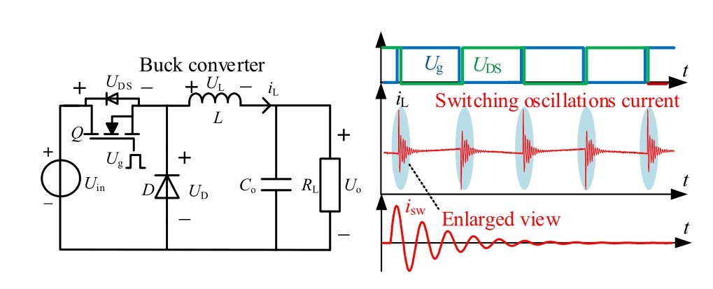
Fig.4.HF switching oscillation current in buck converter [23].
The PWM waveform is characterized by its amplitude(A), duty cycle (D), and period (T), and rise time (τr).The harmonic spectrum is present at discrete frequencies(f), and the spectral envelope can be derived by substituting f = n/T:
where τ = D/T.Spectral limits are employed to gain clearer insights from the harmonic spectrum, emphasizing the effects of rise and fall times and of pulse width.The boundary is established by computing the logarithm of the envelope:

Fig.5(a) displays the harmonic spectrum of the trapezoidal waveform.The first term in (3) shows a constant value.The subsequent two terms exhibit asymptotes with slopes of 20 and 40 dB/decade.This indicates that for every tenfold increase in frequency (the ratio between the two frequencies is 10), the amplitude decreases by 20 dB [24].
The asymptote of the second term in (3) occurs at f1 = 1/πτ, whereas the final asymptote is at f2 = 1/πτr.In Fig.5(b), the harmonic spectrum starts at 0 dB/decade and maintains a value of 2Aτ/T up to the first breakpoint f1 = 1/πτ.After this point, the value drops at a rate of dB/decade until it reaches f2 = 1/πτr, from where the amplitude then decreases at a steeper rate of
 dB/decade.
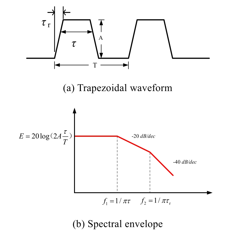
Fig.5.Time-frequency characteristics representing typical PWM output voltage.
The switching speed of a power switching device has a direct impact on its voltage rise time.This switching speed,in turn,impacts the conversion frequency f2;that is to say,the converter using the power device with a higher switching speed will have a higher frequency transition point where the electromagnetic interference amplitude starts to decline at the 40 dB/decade slope, and the amplitude of the excited HF electromagnetic oscillation will be larger.Nowadays, with the large-scale application of SiC devices and the popularity of new energy vehicles [25,26], the switching time of power switching devices is continuously shortened, which greatly increases the intensity of HF interference [27,28].The electromagnetic interference of wide bandgap (WBG) power devices is thus a noteworthy problem [29,30].
1.4 Modeling techniques for the switching characteristics of power electronic devices
1) IGBT switching behavior
The turn-on process of an insulated-gate bipolar transistor(IGBT) under inductive load conditions is described in [31].Fig.6 illustrates the chopper circuit used to model inductive switching.This circuit employs a large inductor L0 with an equivalent series resistance R0.The gate circuit model includes gate resistance Rg and gate parasitic inductance Lg.Parasitic inductance Le represents the inductance of the IGBT emitter, whereas parasitic inductance Ls represents the remainder of the switching loop inductance.The Rs-Cs snubber circuit can be used to reduce ringing during diode turn-off.The load current IL commutates from the freewheeling diode to the IGBT.The diode reverse recovery current flows through the IGBT, causing a significant overcurrent [32].
2) SiC MOSFET switching behavior
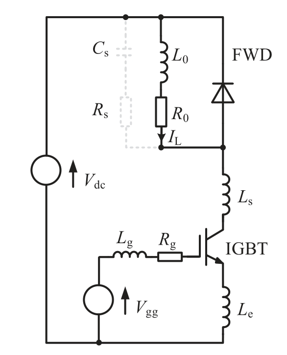
Fig.6.Circuit for IGBT inductive turn-on [31].
The switching characteristics of SiC MOSFETs are typically analyzed using a double pulse test (DPT) circuit,with its parasitic parameters shown in Fig.7.According to the research thus far,the gate inductance has little influence on the switching behavior and thus is not considered in Fig.7 [33].
Stage One:Upon the application of a positive drive signal Vdrive_on, the gate-drain capacitance (Cgd) and gatesource capacitance (Cgs) start charging until the gatesource voltage (Vgs) exceeds the threshold voltage (Vth)[34].During this phase, the MOSFET remains in the OFF state, gate resistance (Rg) and current  , as well as the voltages Vgd and Vgs across Cgd and Cgs respectively,satisfy the following equations:

Stage Two: Once Vgs exceeds Vth, the channel current starts to increase, approximately proportionally to (Vgs- .At this stage, the drain current (Id) adheres to Eq.(7), where gm is the transconductance, a nonlinear function of Vgs.During this phase,Id from Eq.(4)is much larger than Ig, allowing Ig to be neglected.By integrating Eqs.(4) through (8), a state equation that describes this phase is established [34].

Stage Three: Once Vgs reaches the Miller plateau voltage, equal to (Io/gm + Vth), the drain-source voltage(Vds) begins to decrease toward the on-state voltage.Simultaneously,the voltage(Vd)across the parasitic diode capacitance (Cd) increases, resulting in a reverse recovery current being injected into the MOSFET channel.Eqs.(9) and (10) are then derived.
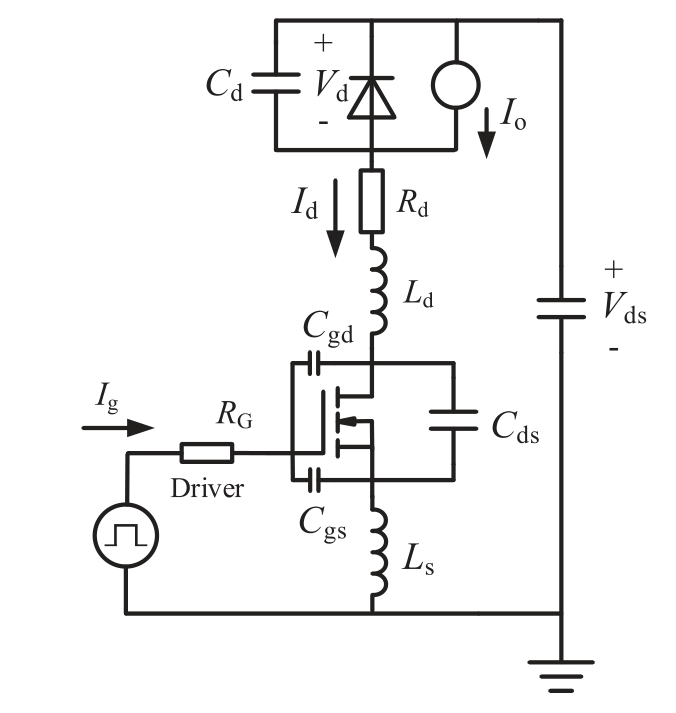
Fig.7.Equivalent DPT circuit with parasitic parameters [34].

By combining Eqs.(1)-(6), (7), (9), and (10), a state equation that can describe related parameters is established.
Stage Four: In this phase, Vgs increases to Vdrive_on.Meanwhile, Id can be expressed as Eq.(11), where Rds_on is the on-state resistance of the MOSFET.Eqs.(4)through(6) and Eqs.(9) through (11) are combined to derive the state equation for this phase.At this point, the turn-on process is complete.
During the turn-offprocess,after a negative drive signal is applied, Vgs begins to fall, reaching the Miller plateau voltage.The subsequent stages are the voltage rise phase and the current fall phase.As a result of the symmetry of the switching process, their state equations correspond to those of the voltage fall and current rise phases,respectively, except for the drain current Id.
When VgsVgsVth, the MOSFET operates in the ohmic region, satisfying Eq.(11).When Vgs <Vgs Vth,the MOSFET is in the saturation region, satisfying Eq.(7), where the transconductance is a nonlinear parameter reflected during the turn-offprocess.
Once the MOSFET is fully turned off,the output capacitance resonates with the parasitic inductance.This phase can be represented with a state equation combining Eqs.(4) through (6), (8), and (12) [34].
3) GaN HEMT switching behavior
To analyze the switching behavior of gallium nitride(GaN) high-electron-mobility transistors (HEMTs), an LTspice model of an inductive-load-clamped doublepulse tester(DPT)was constructed.The simulation model includes the GaN HEMT phase leg and parasitic elements,as depicted in Fig.8 [35].
The lower GaN transistor serves as the device under test(DUT).The connections of the drain and source for this GaN device are configured in an interleaved land grid array (LGA) package, resulting in ultra-low parasitic inductance.Consequently, the GaN transistor model includes only nonlinear parasitic capacitance and parasitic resistance [36], as illustrated in Fig.8.The gate-source voltage Vgs is 5 V, with two distinct resistors, Rgon and Rgoff, used to separately adjust the turn-on and turn-offspeeds.
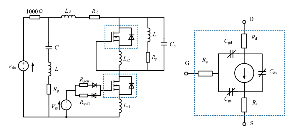
Fig.8.Simulation model of double-pulse test circuit [35].
The upper transistor is either permanently off(for varying parasitic elements)or is also switched on/offusing separate gate resistors, referred to as Rgoff,2 and Rgon,2 (e.g.,for varying gate resistance and dead time).It is modeled with the parasitic elements of the inductive load and DC capacitor.
These factors typically do not significantly affect switching behavior.However, the parasitic inductance of the capacitor and the parasitic capacitance of the inductor should be minimized as much as possible.Additionally,stray inductance Lδ and resistance Rδ are introduced into the power loop.The common source inductance LS1 and LS2 associated with each GaN device are also considered.The power loop inductance Lδ and the source inductance LS1 or LS2 are two primary parasitic inductances affecting the switching transients.To analyze the switching behavior of GaN HEMTs, parameters such as Lδ, LS1, Cp, Rgoff,and Rgon can be varied [35].
1.5 HF modeling of parasitic components
HF modeling for system components must consider parasitic parameters.Generally, existing HF modeling techniques are categorized under behavioral modeling and equivalent-circuit modeling.In behavior modeling, a black box method with independent sources for multiport networks was used.This technique relies on experimental data to determine model parameters, making it particularly suitable for system-level evaluations.By contrast, detailed modeling considers the specific characteristics of circuit components and uses a device-based methodology, incorporating physics-based models to account for all parasitic elements [37].
1) Power electronics switching device
Considering the nonlinearity of the switching device increases the complexity and simulation time of the model.To implement a more analytical method, the switching cycle is divided into separate time intervals to accurately capture the nonlinear behavior of the stray capacitance within the IGBT [38,39].The equivalent circuit of an IGBT includes interconnect inductance, lead inductance,and stray capacitance, as shown in Fig.9(a).A piecewise linear IGBT model is illustrated in Fig.9(b).Herein,Ron,which represents the on-state resistance,can be found in the device datasheet, whereas the capacitance is determined through standard measurement methods.In Fig.9(b), Ccg and Ceg denote the parasitic capacitances of the collector and emitter of the IGBT, respectively, with respect to ground.The total junction capacitance, including both the collector-emitter capacitor of the IGBT and the anti-parallel diode, is represented by C0.
2) Power capacitor
The equivalent circuit of the capacitor is shown in Fig.10.Herein, Ccap represents the ideal capacitor, and Rp represents the insulation resistance corresponding to the DC leakage current.The equivalent series resistance(Rs) models the heat dissipation of internal components,and Lcap represents the equivalent series inductance.
3) Electric machines
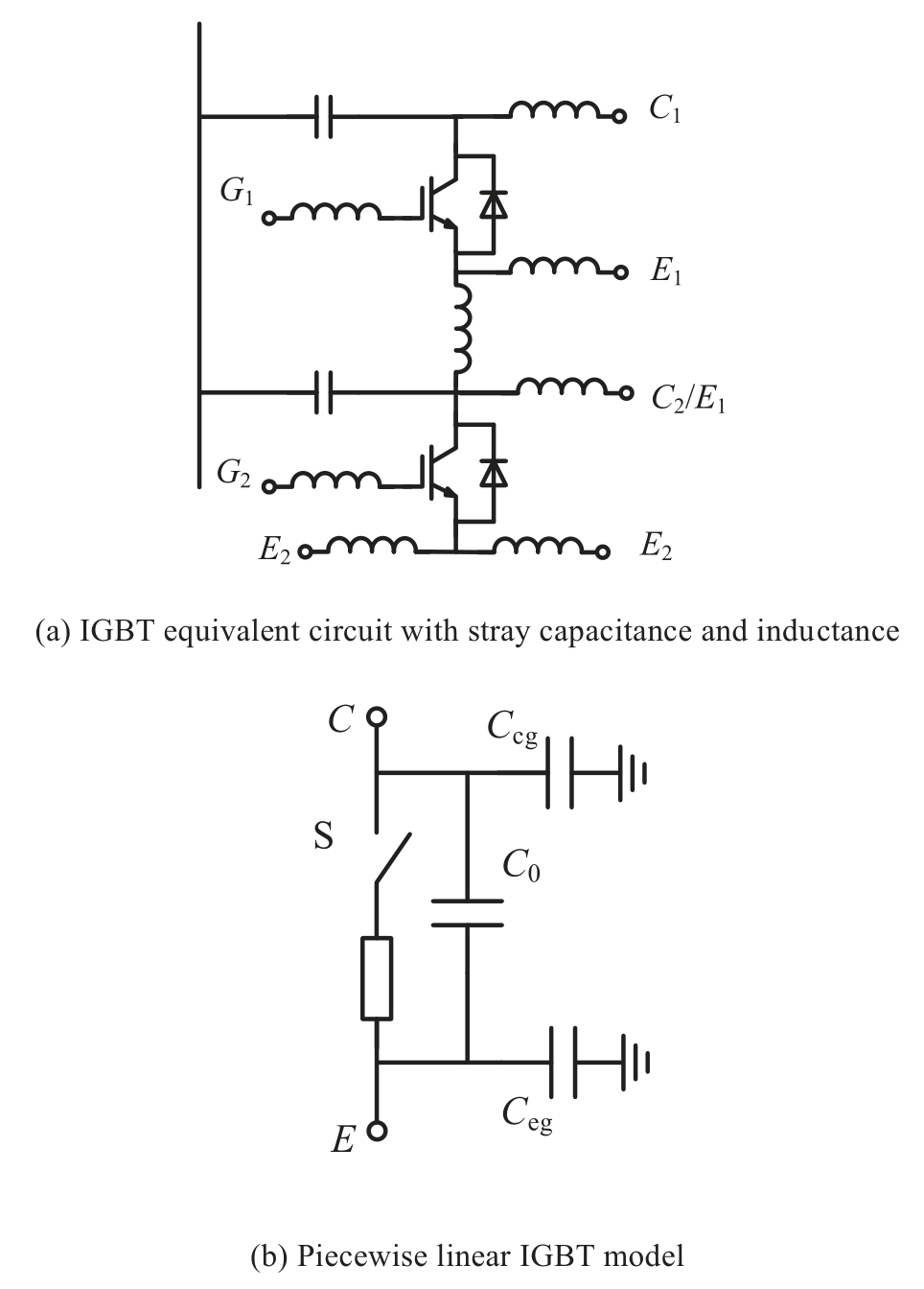
Fig.9.Typical IGBT modes [24].
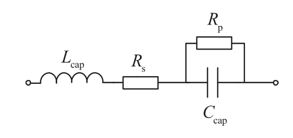
Fig.10.Equivalent circuit of a capacitor.
Electric machines are typically inductive at low frequencies.HF models are essential for analyzing electromagnetic interference.At elevated frequencies, electric machines tend to exhibit increased capacitive behavior, with the stray capacitance between motor windings and the casing serving as the main impedance.Fig.11 shows the HF model of a single-phase lumped circuit for an induction motor.The parasitic elements between the stator windings and the motor casing, including resistance and capacitance,are indicated by Rg1,Cg1,Rg2,and Cg2.The leakage inductance of the stator windings is represented by Ld,whereas the HF core loss is denoted by Re.
4) Power cable
Analogous to motor modeling, cable modeling can employ distributed models.For long cables, a distributed parameter model can be employed because it represents them through the connection of multiple identical RLC segments in series [40].Fig.12 shows the π-type modeling of long cables [41], where Rcab and Lcab represent shortcircuit characteristics, whereas Ccab components represent open-circuit impedance characteristics.
1.6 HF equivalent circuit of power electronics converter
A high dv/dt is produced by the fast switching of power devices in the power converter, creating HF conducted paths through parasitic elements.Identifying the primary mechanisms and dominant modes of HF interference is crucial for analyzing, predicting, and suppressing these noises.The modes of HF interference vary among different power electronic converters.
1) AC converter
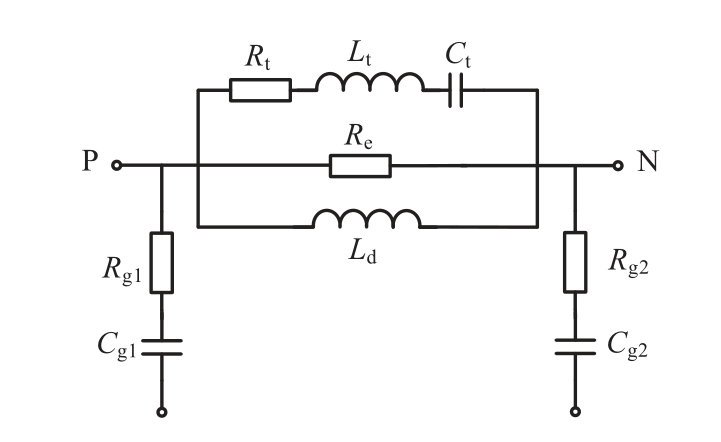
Fig.11.HF model of an induction motor.
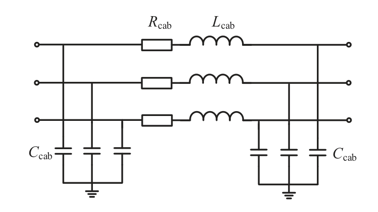
Fig.12.Equivalent circuit of a power cable [24].
For a typical inverter-fed machine system, under steepsided switching voltage excitation, the switching transient current induces multi-mode electromagnetic oscillations through various HF coupling paths, as illustrated in Fig.13 [42,43].The inverter switch phase emits the HF differential-mode current iHFDM, which then returns through the parasitic terminal capacitor Ct of the machine winding [44,45].The HF common-mode current iHFCM exits through the terminal capacitor into the ground and reenters the inverter via the parasitic capacitor Cheat [46].
2) DC converter
Fig.14(a) presents the HF equivalent circuit of a nonisolated buck converter, including parasitic parameters.The inductor, composed of a multi-turn electromagnetic coil insulated with a protective layer, generates a distributed capacitance Cp between its turns.The equivalent series resistance corresponding to HF magnetic core losses in the inductor is represented by Req_L.The inductance and resistance of the oscillation loop are also represented as Lloop and Rloop, respectively [23].
In a typical isolated flyback converter,parasitic parameters affect HF transient analysis.Besides the nonlinear parasitics of the switching device, the HF parasitics of the transformer, such as leakage inductance and distributed capacitance, should be considered.These include parasitics between winding turns, winding layers, different windings,and the shielding layer.The HF model incorporating these parasitics is shown in Fig.14(b).
1.7 Scenario and practical case of HF interference problem in power system
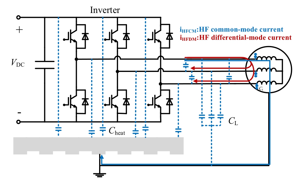
Fig.13.Dominant HF interference modes in inverter-fed motor system.
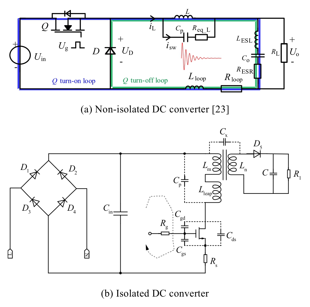
Fig.14.HF equivalent circuit.
The advancement of digital intelligence and power electronification in new power systems introduces diverse heterogeneous devices, complicating the operational electromagnetic environment.HF interferences from communication carriers, high-order harmonics, and HF pulses induced by power electronics are quite complex, timevarying,and unstable,posing risks to power-system safety operation.Typical scenarios include high-voltage cables and substations.HF interference on cables arises from conductor characteristics and electromagnetic coupling.HF electromagnetic fields induce interference currents in cables.In addition, electromagnetic coupling between power cables and surrounding components exacerbates HF interference [47,48].Advanced 5G equipment and inverter-fed machines (e.g., variable-frequency air conditioners)in substations may generate electromagnetic interference through switching-mode operations and HF pulses[49,50].HF interference from power electronics in distribution networks can disrupt communication systems [51,52],cause data transmission errors,and impact condition monitoring and control [53,54].
Practical Case: In a 500-kV cable tunnel, the cable PD monitoring system experiences significant HF noise and interference.Analysis indicates that these problems originate primarily from the power electronic drivers of LED tunnel lighting.LED drivers contain high-speed switching power devices,which,during operation,trigger high dv/dt on parasitic parameters, resulting in HF interference.Fig.15 illustrates how the characteristics of the measured HF pulse current from the LED lights closely resemble those of the PD monitoring signal,which can readily cause interference,whereas Fig.16 illustrates how turning offthe LED lights significantly reduces the amplitude and intensity of HF interference.Therefore,attention must be given to the HF interference caused by power electronics equipment.
2 HF interference suppression methods in power electronics
2.1 Electromagnetic interference classification
HF electromagnetic interference noise propagates primarily through HF currents (conduction) or via higherfrequency electromagnetic fields and waves (radiation)[55].These types are classified as shown in Fig.17(a).Electromagnetic interference is categorized into radiated and conducted types based on the operating frequency.
The intensity of HF electromagnetic interference is influenced not only by the noise source but also by the propagation path, which is determined by the physical characteristics of the noise.Conducted electromagnetic interference typically occurs at lower frequencies, below 30 MHz.In power electronics, conduction current is a key source of electromagnetic noise, which is categorized into common mode and differential mode based on its propagation route [56,57], as depicted in Fig.17(b).
Common-mode noise, a primary type of conducted electromagnetic interference, falls under the asymmetric mode category.In Fig.17(b), a common-mode noise source generates noise current that flows uniformly in the phase and neutral lines.Conversely, the noise current generated by a differential-mode noise source flows in opposite directions [58,59].
Herein, IP denotes the phase current, whereas IN indicates the neutral line current.Meanwhile, Icm represents the common-mode current, and Idm represents the differential-mode current.

Common-mode current results from parasitic capacitance within the system, leading to current flow in the ground wire.The common-mode conduction circuit is linked to the stray parameters of the system with respect to ground,resulting in complex impedance characteristics.The conduction current in relation to 1 μA can be expressed as follows:
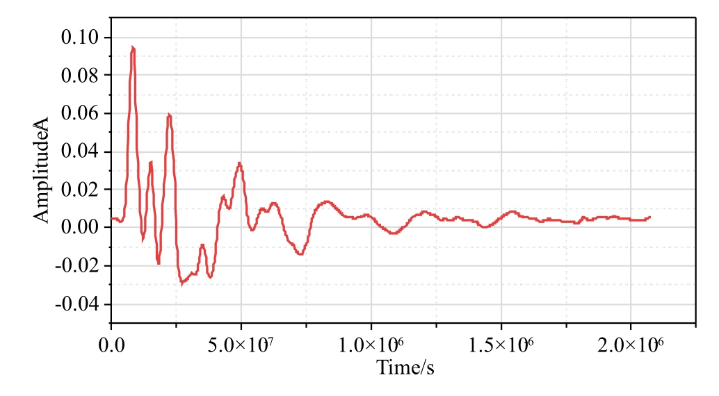
Fig.15.Measured HF common-mode current of LED lamp.
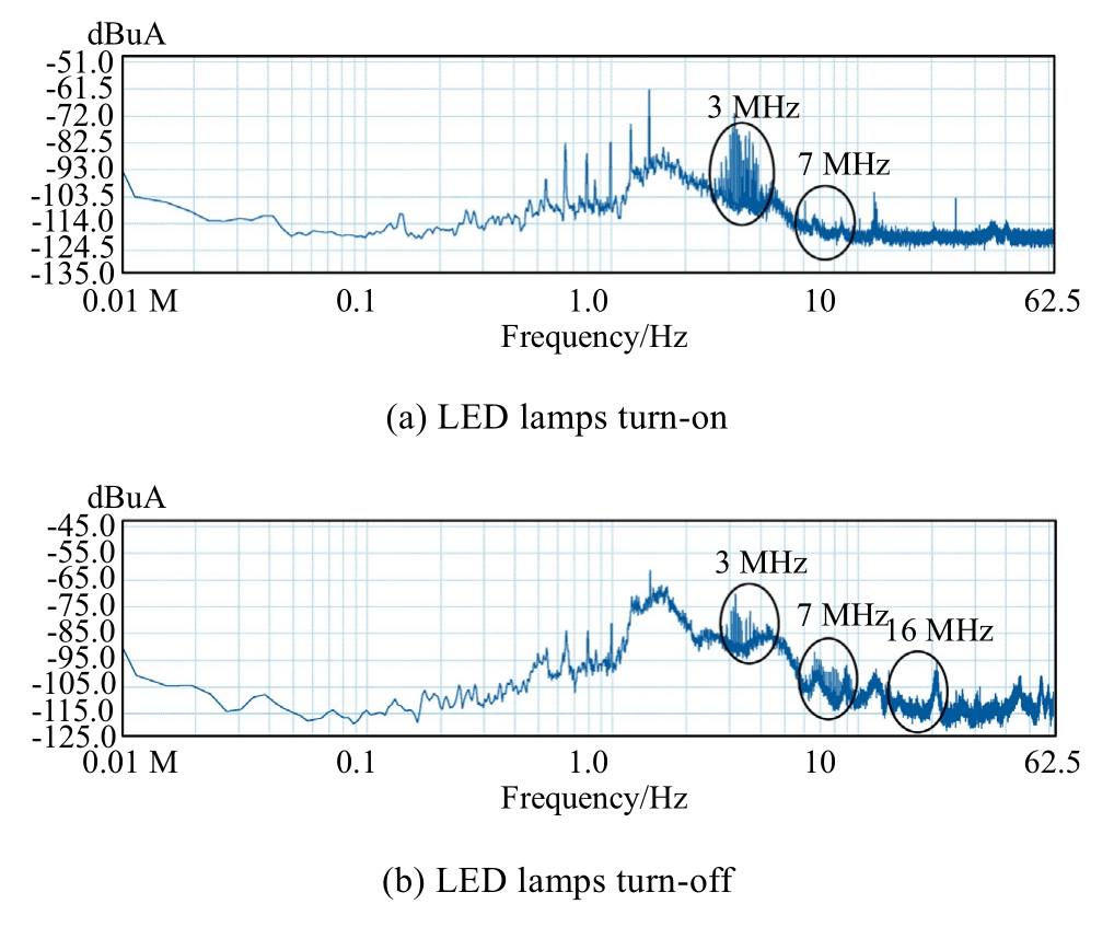
Fig.16.Measured frequency spectrum of ground current in underground high-voltage cables.
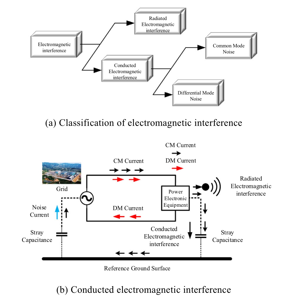
Fig.17.Electromagnetic interference.

In differential-mode interference, HF signals are transmitted as voltage or current between two wires with differing magnitudes and phases.This can involve either intentional differential signals or unintended electromagnetic noise.
2.2 HF interference suppression technology
Existing HF electromagnetic interference suppression technologies focus on two main approaches: excitation source-based and conduction path-based.The rapid and frequent switching of power devices acts as the excitation source for HF electromagnetic oscillations.Through the proper regulation of the switching sequence or the transient process,the HF excitation can be effectively reduced,thereby suppressing the induced HF interference.
1) HF suppression from source
The switching sequence regulation method, known as variable switching frequency PWM, involves changing switching frequency characteristics [60,61].According to Parseval’s theorem,the total energy of a signal is invariant between the time and frequency domains.Expanding the switching frequency band can reduce the component peak,thus lowering the peak of electromagnetic interference noise.Canceling common-mode voltage utilizes the multi-vector combination of the parallel converter to synthesize and cancel the effective vector, ensuring the elimination of common-mode voltage [62].
The switching transient control method employs active gate control[63,64]and increased gate resistance[65].The principle of active gate drive involves collecting the collector voltage signal through resistive voltage division and comparing it with a reference waveform.Fig.18 shows the closed-loop gate drive scheme using analog control of the collector voltage trajectory [62,66].
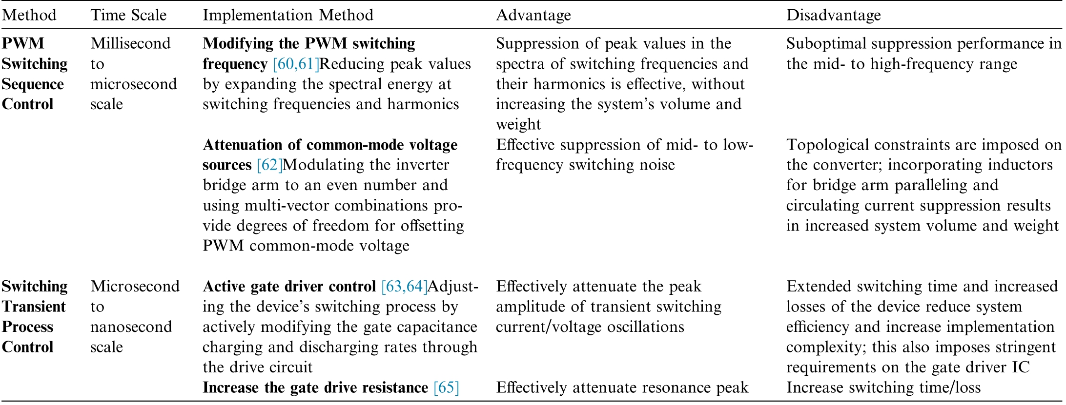
Controlling switching transients can lower switching speed and the resulting dv/dt and di/dt, thereby suppressing switching oscillation.Table 1 provides an analysis of existing suppression techniques from the perspective of excitation sources.
2) HF suppression from path
HF parasitic effects create coupling paths for HF oscillating currents.Managing these effects involves regulating the conduction path impedance and optimizing the main circuit structure,which helps suppress HF electromagnetic oscillation and its impact on power electronics.
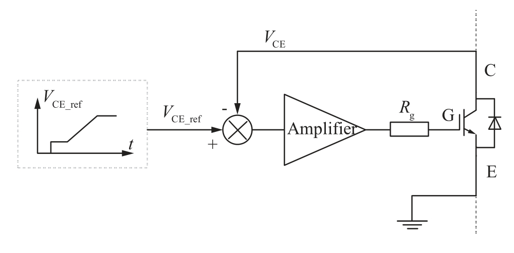
Fig.18.Typical active gate driver.
Conduction path impedance control methods include electromagnetic interference (EMI) passive filtering[67,68] and active filtering [23,69-71].
The primary purpose of an EMI filter, which is placed at the power entry point of a device, is to prevent noise from flowing out of or into the device.A typical EMI filter is illustrated in Fig.19.It includes X capacitors connected between the phase (P) and neutral (N) lines to shunt differential-mode noise.Differential-mode noise exists between the AC line and the neutral conductor, with a phase difference of  between them.The differentialmode noise current does not pass through the protective earth(PE)line.If high attenuation is required,suppression chokes can be added.The filter also contains a commonmode choke with windings in series with the P and N lines,and Y capacitors that connect the power line conductors to ground [72].
To mitigate HF noise currents, EMI passive filtering employs inductive elements to intercept them and capacitive bypass components to diminish them,thereby mitigating electromagnetic interference [73,74].To suppress electromagnetic interference generated by systems,various types of passive EMI filters can be designed.These include band-pass filters, which allow signals within a specific frequency range to pass while attenuating frequencies outside that range, and band-stop filters, which are used to suppress signals within a specific frequency band,thereby preventing interference at particular frequencies.Fig.20 presents the architecture of a conventional three-phase motor drive system, which incorporates passive filters on both the DC and AC sides to attenuate noise.
EMI active filtering works by offsetting the interference signal with a compensation signal that is out of phase with the interference, achieving a filtering effect [75,76].This compensation signal is generated by adjusting active circuit elements, such as transistors, to counteract the interfering signal.EMI active filters are classified into feedforward and feedback types based on their sensing and compensation positions.They can also be categorized into four types.Fig.21 illustrates the basic principle,where ZS denotes the network impedance of the line impedance stabilization network(LISN),Zn indicates the internal resistance of the noise source, and in refers to the associated noise current.
The circuit structure optimization design method[77,78] mitigates the adverse effects of HF switching oscillation by employing low parasitic parameter structures[79]or external buffer elements [80,81].For instance, a common circuit optimization approach involves adding a buffer circuit to absorb spike signals generated by switching actions.Table 2 provides an analysis of suppression techniques from the perspective of conduction pathways.
Table 1 Comparison of existing HF electromagnetic interference suppression technologies from excitation source.
MethodTime ScaleImplementation MethodAdvantageDisadvantage PWM Switching Sequence Control Millisecond to microsecond scale Modifying the PWM switching frequency [60,61]Reducing peak values by expanding the spectral energy at switching frequencies and harmonics Suppression of peak values in the spectra of switching frequencies and their harmonics is effective, without increasing the system’s volume and weight Suboptimal suppression performance in the mid- to high-frequency range Attenuation of common-mode voltage sources [62]Modulating the inverter bridge arm to an even number and using multi-vector combinations provide degrees of freedom for offsetting PWM common-mode voltage Effective suppression of mid- to lowfrequency switching noise Topological constraints are imposed on the converter; incorporating inductors for bridge arm paralleling and circulating current suppression results in increased system volume and weight Switching Transient Process Control Microsecond to nanosecond scale Active gate driver control [63,64]Adjusting the device’s switching process by actively modifying the gate capacitance charging and discharging rates through the drive circuit Extended switching time and increased losses of the device reduce system efficiency and increase implementation complexity; this also imposes stringent requirements on the gate driver IC Increase the gate drive resistance [65]Effectively attenuate resonance peakIncrease switching time/loss Effectively attenuate the peak amplitude of transient switching current/voltage oscillations
The suppression of electromagnetic interference in isolated power electronic converters can be achieved using several techniques specific to these converters.Examples include the shield-cancelling technique [82], passive cancelling method [83], shield-passive cancelling compound[84],phase-shift control full bridge converter[85],and split winding structure [86].
2.3 Performance comparison of HF interference suppression techniques in power electronics
Although PWM switching sequence regulation technologies can effectively suppress the switching frequency and its harmonic peaks,methods like changing the switching frequency or canceling the common-mode voltage are limited to the PWM time scale and are less effective in higher-frequency bands.Conversely, switching transient control methods can significantly reduce the amplitude of switching transient currents or voltage oscillations.However, these methods tend to increase the switching time and losses of power devices,reduce system efficiency,introduce higher complexity, and demand precise control of the drive circuit.
The basic structure and design method of EMI passive filtering are already mature and proven to effectively suppress oscillations of power electronic switches in both high- and low-frequency bands.However, its inevitable parasitic parameters lead to problems such as attenuation of HF suppression performance[87],difficulty in suppressing local resonance points[88],and a significant increase in electromagnetic oscillation amplitude due to HF resonance [89].On the other hand, active EMI filters offer advantages like small size and light weight,but exhibit limited suppression performance in bands above MHz because of factors such as HF signal bandwidth, response speed, and operational amplifier gain bandwidth product.Additionally,the complex structure of active filters reduces their reliability.
Circuit structure optimization effectively suppresses switch current/voltage oscillations, reduces stray capacitance to ground, and improves HF damping.However,the reduction of parasitic inductance is limited, manufacturing costs are high,and system losses increase.As power density and efficiency in power electronic devices continue to rise, the potential for optimization and the effectiveness of these designs become progressively limited.
Employing the shield-cancellation technique requires adjacent windings with identical turns and winding directions.Compared to single-layer shielding, shield cancellation effectively eliminates electric field coupling between primary and secondary windings, although it involves a more complex shielding structure.For phase-shift control of full-bridge converters, combining symmetric circuit design with passive cancellation technologies yields the most effective suppression.A split-winding topology can be strategically implemented to comprehensively mitigate common-mode interference across both the input and output stages,but it requires additional winding and compensation capacitance and exhibits poor HF characteristics.
In summary, existing HF electromagnetic interference suppression technologies have different characteristics and limitations considering practical perspectives, such as efficiency volume, complexity, switching transients,and attenuation performance across different frequency bands, as compared in Fig.22.Given the constraints of higher-operating-frequency bands and increased power density in power electronics equipment, current methods struggle to balance suppression effectiveness, efficiency,and implementation complexity, simultaneously.
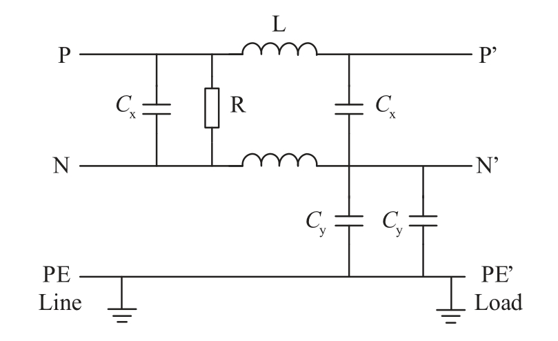
Fig.19.Typical EMI filter [72].
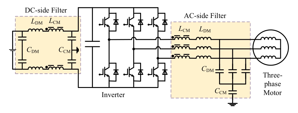
Fig.20.Architecture of passive EMI filters in DC-fed inverter motor drive [62].
3 Challenges and suggestions
The usage share of power electronics equipment within new electrical power systems is growing.Power electronics offer high efficiency and flexibility in energy conversion,but the high-speed switching of power devices causes significant HF interference problems.The electromagnetic oscillation during switching transients is the inherent resonant response of power electronic systems under the coupling of HF parasitic parameters.It exhibits broadband,multimodal forms, and difficult-to-suppress HF resonant peaks.
Power electronic converters utilizing WBG devices offer greater efficiency and reduced weight compared to those provided by traditional silicon-based counterparts.As power grade and density requirements increase in new power systems, WBG devices like SiC and gallium nitride become essential for high-power applications [90,91].These devices enable more efficient and compact equipment.However, their faster switching speeds and lower parasitic inductance and junction capacitance generate significant HF components, reaching frequencies of up to 100 MHz, exacerbating HF interference problems.
In the field of HF interference suppression in power electronics, although many technical solutions have already been developed, there remain a number of challenges in practical application.
1) Accurate modeling and prediction of HF interference
The goal of modeling is to gain a thorough understanding of the generation, propagation, and prediction of HF interference.Accurate modeling is necessary to predict and analyze its propagation paths and effects.However,creating accurate HF models is difficult as a result of complex device coupling and variable parasitic parameters,which change with equipment health and operating conditions [92,93].Existing HF models are effective only under specific conditions.In practice, operating conditions are often complex and dynamic; for instance, changes in converter operating conditions significantly alter the source impedance[94],affecting the suppression efficacy of the filter.Additionally, dynamic changes in operating temperature impact device characteristics, making noise characteristics across a wide temperature range more complex and increasing the difficulty of corresponding HF modeling [95].
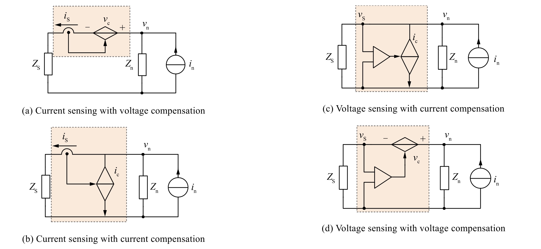
Fig.21.Architecture of active EMI filter.
Table 2 Current status and analysis of HF electromagnetic oscillation suppression technologies from conduction path.
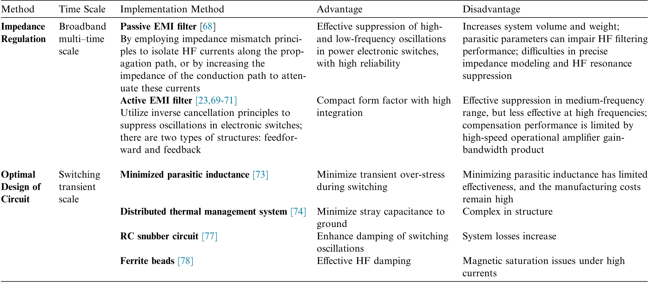
MethodTime Scale Implementation MethodAdvantageDisadvantage Impedance Regulation Broadband multi-time scale Passive EMI filter [68]By employing impedance mismatch principles to isolate HF currents along the propagation path, or by increasing the impedance of the conduction path to attenuate these currents Effective suppression of highand low-frequency oscillations in power electronic switches,with high reliability Increases system volume and weight;parasitic parameters can impair HF filtering performance; difficulties in precise impedance modeling and HF resonance suppression Active EMI filter [23,69-71]Utilize inverse cancellation principles to suppress oscillations in electronic switches;there are two types of structures: feedforward and feedback Compact form factor with high integration Effective suppression in medium-frequency range, but less effective at high frequencies;compensation performance is limited by high-speed operational amplifier gainbandwidth product Optimal Design of Circuit Switching transient scale Minimized parasitic inductance [73]Minimize transient over-stress during switching Minimizing parasitic inductance has limited effectiveness, and the manufacturing costs remain high Distributed thermal management system [74] Minimize stray capacitance to ground Complex in structure RC snubber circuit [77]Enhance damping of switching oscillations System losses increase Ferrite beads [78]Effective HF dampingMagnetic saturation issues under high currents
2) High-efficiency suppression of HF resonance peaks
Parasitic parameters are common non-ideal factors often overlooked in HF suppression techniques.These parasitic effects can undermine the noise suppression effectiveness of HF suppression devices and introduce additional propagation paths, reducing performance at higher frequencies [96].Resonance-type noise induced by HF switching transient increases the attenuation requirements for EMI filters in the HF domain[97].The inherent parasitic parameters of EMI filters can negatively impact their HF attenuation performance.The interactions between filter impedance and conductive paths, coupled with self-resonance effects, present challenges for effective HF oscillation suppression [98].Consequently, it is often necessary to overdesign filters.Accurately identifying dominant HF interference modes is difficult without precise parameter models, complicating efficient directional suppression.
To address HF interference from power electronics, a range of technical measures must be comprehensively applied.During the design phase of power electronics equipment,optimizations can be made based on the specific application, such as reducing power transmission path lengths, minimizing electromagnetic interference sensitivity, using low-radiation power transistors, and employing magnetic components to lower interference generation.Designing stable and reliable power supply systems,including filters and regulators,is crucial to ensure consistent power delivery and minimize interference from power fluctuations under complex conditions.Additionally, it is important to evaluate the access and HF interference levels of power electronics equipment and develop appropriate standards.Although electromagnetic interference standards have already been established for discrete power electronics, standards for specific applications, such as cable tunnels and substations, remain lacking.Furthermore,conducting HF interference access tests and electromagnetic environment assessments before connecting power electronics to the power system is essential.
4 Conclusion
This paper offers an in-depth analysis of HF interference problems and challenges in contemporary power systems stemming from power electronics equipment.It begins by analyzing the primary cause of HF interference:the resonant response of system distributed parameters to high-speed switching transients.As WBG devices gradually replace silicon-based devices, HF interference in new power systems is expected to intensify.This paper further explores the types and conduction paths of HF interference, highlighting the importance of addressing HF common-mode interference.Owing to the complex HF coupling effect in grounding systems,common-mode interference may adversely affect condition monitoring of highvoltage cable and distribution networks.Finally,the existing methods for HF interference suppression are summarized, detailing their principles, characteristics, and applicability.Current challenges include accurate HF modeling, the impact of non-ideal effects, varying operating conditions, and suppression of HF resonant peaks,which should be comprehensively considered based on the specific application scenario.Effective solutions require optimizing power electronics equipment design for HF interference and coupling, along with rigorous testing and evaluation to mitigate potential problems.
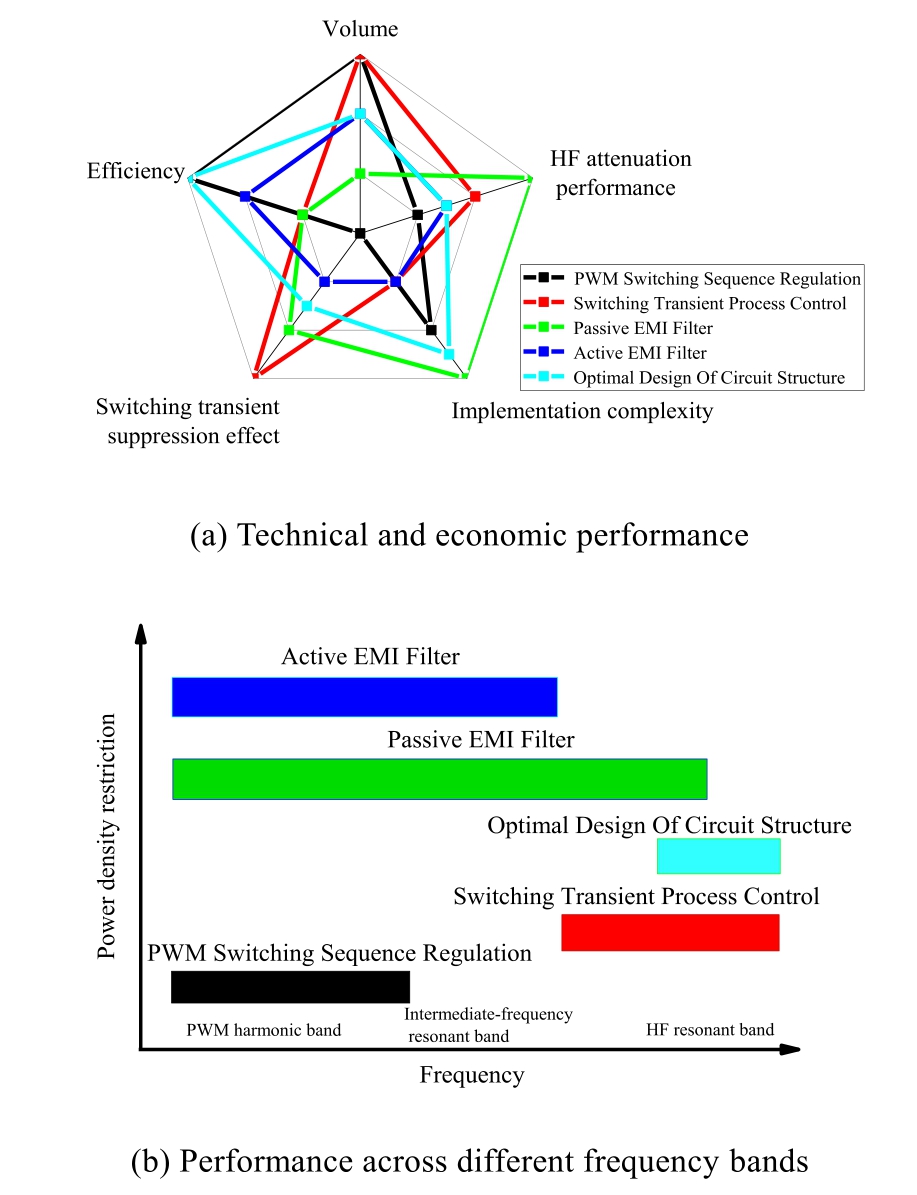
Fig.22.Qualitative comparison of different HF interference suppression techniques.
Declaration of competing interest
The authors declare the following financial interests/personal relationships which may be considered as potential competing interests: Xing Lei, Yundong Hu, Xizhou Du and Ting Ye report financial support was provided by State Grid Shanghai Municipal Electric Power Company.Xing Lei, Yundong Hu, Xizhou Du and Ting Ye reports a relationship with State Grid Shanghai Municipal Electric Power Company that includes: employment.If there are other authors, they declare that they have no known competing financial interests or personal relationships that could have appeared to influence the work reported in this paper.
Acknowledgments
This work was supported by the science and technology project of State Grid Shanghai Municipal Electric Power Company (No.52094023003L).
References
-
[1]
B.Zhang,M.Zhang,T.Dong,et al.,Design of digital twin system for DC contactor condition monitoring,IEEE Trans.Ind.Appl.59(4) (2023) 3904-3909. [百度学术]
-
[2]
X.Suo, S.Zhao, Y.Ma, et al., New energy wide area complementary planning method for multi-energy power system,IEEE Access 9 (2021) 157295-157305. [百度学术]
-
[3]
H.Li, B.Li, Z.Luo, et al., Power supply reliability enhancement for low-voltage distribution area with power quality improvement function, IEEE Access 10 (2022) 130619-130631. [百度学术]
-
[4]
A.M.Alcaide,G.Buticchi,A.Chub,et al.,Design and control for high-reliability power electronics: state-of-the-art and future trends, IEEE J.Emerg.Selected Topics Ind.Electron.5 (1)(2023) 50-61. [百度学术]
-
[5]
M.K.Zadeh, R.Gavagsaz-Ghoachani, S.Pierfederici, et al.,Stability analysis and dynamic performance evaluation of a power electronics-based DC distribution system with active stabilizer, IEEE J.Emerg.Selected Topics Ind.Electron.4 (1)(2015) 93-102. [百度学术]
-
[6]
M.Bajaj, A.K.Singh, M.Alowaidi, et al., Power quality assessment of distorted distribution networks incorporating renewable distributed generation systems based on the analytic hierarchy process, IEEE Access 8 (2020) 145713-145737. [百度学术]
-
[7]
W.Lu, J.Duan, L.Cheng, et al., Evaluation method for electromagnetic interference complexity of high voltage switch based on feature extraction and GCC-GRU network, High Volt.(2024). [百度学术]
-
[8]
F.Abid,T.Busatto,S.K.Ro¨nnberg,et al.,Intermodulation due to interaction of photovoltaic inverter and electric vehicle at supraharmonic range, in: 17th International Conference on Harmonics and Quality of Power (ICHQP), IEEE, 2016, pp.685-690. [百度学术]
-
[9]
M.Klatt, J.Meyer, P.Schegner, et al., Characterization of supraharmonic emission caused by small photovoltaic inverters,in: Mediterranean Conference on Power Generation,Transmission, Distribution and Energy Conversion (MedPower),IET, 2016, pp.1-6. [百度学术]
-
[10]
X.Du,Z.Yao,Y.Chen, et al.,Research on impact mechanism of high-frequency interference from power electronic equipment on PD monitoring of high-voltage cables,in:International Conference on HVDC (HVDC), IEEE, 2024, pp.751-755. [百度学术]
-
[11]
S.Pourfarrokh, J.Adabi, F.Zare, A new grid-connected asymmetrical multilevel converter for PV application, IEEE Trans.Power Electron.39 (9) (2024) 11256-11265. [百度学术]
-
[12]
L.Ji, G.ZhenYu, Z.Xue You, et al., One high voltage regulation method and related control strategy in the DC transmission system,Recent Adv.Electric.Electron.Eng.(Formerly Recent Patents Electric.Electron.Eng.17 (2) (2024) 202-215. [百度学术]
-
[13]
Y.L.Sun, W.Y.Liu, N.B.Wang, et al., The coordination control method of dynamic reactive power compensation equipment based multi-objective, Adv.Mat.Res.724 (2013) 635-640. [百度学术]
-
[14]
W.Huang,X.Zhang,K.Li,et al.,Resilience oriented planning of urban multi-energy systems with generalized energy storage sources, IEEE Trans.Power Syst.37 (4) (2021) 2906-2918. [百度学术]
-
[15]
M.Bollen,S.Ro¨nnberg,F.Zavoda, et al., Consequences of smart grids for power quality: overview of the results from CIGRE joint working group C4.24/CIRED, in: IEEE PES Innovative Smart Grid Technologies Conference Europe (ISGT-Europe).IEEE,2017, pp.1-6. [百度学术]
-
[16]
F.Liu, S.Lin, J.Ma, et al., Data-driven mode identification method for broad-band oscillation of interconnected power system,IEEE Sens.J.22 (15) (2022) 15273-15283. [百度学术]
-
[17]
P.Ray, P.K.Ray, S.K.Dash, Power quality enhancement and power flow analysis of a PV integrated UPQC system in a distribution network, IEEE Trans.Ind.Appl.58 (1) (2021) 201-211. [百度学术]
-
[18]
C.A.Charalambous, A.Demetriou, A.L.Lazari, et al., Effects of electromagnetic interference on underground pipelines caused by the operation of high voltage AC traction systems: the impact of harmonics, IEEE Trans.Power Delivery 33 (6) (2018) 2664-2672. [百度学术]
-
[19]
A.J.Collin,J.Meyer,P.Davari,et al.,Modelling the unintentional emissions of single-phase power electronic converters for distortion studies in the 2-150 kHz range,IEEE Trans.Power Delivery 39(6)(2024) 3126-3138. [百度学术]
-
[20]
D.Darmawardana,S.Perera,D.Robinson,et al.,Investigation of high frequency emissions (supraharmonics) from small, grid-tied,photovoltaic inverters of different topologies,in:18th International Conference on Harmonics and Quality of Power (ICHQP), IEEE,2018, pp.1-6. [百度学术]
-
[21]
T.Wohlfahrt, C.Waniek, J.M.A.Myrzik, et al., Supraharmonic disturbances: lifetime reduction of electronic mass-market equipment by the aging of electrolytic capacitors, in: 18th International Conference on Harmonics and Quality of Power(ICHQP), IEEE, 2018, pp.1-6. [百度学术]
-
[22]
L.Yang, S.Wang, J.Feng, Advances in electromagnetic interference modeling and noise reduction for adjustable speed motor drive systems, in: IEEE International Symposium on Electromagnetic Compatibility & Signal/Power Integrity(EMCSI).IEEE, 2017, pp.249-254. [百度学术]
-
[23]
Z.Zhang,Y.Hu,X.Chen,et al.,A review on conductive commonmode EMI suppression methods in inverter fed motor drives,IEEE Access 9 (2021) 18345-18360. [百度学术]
-
[24]
T.Liu,T.T.Y.Wong,Z.J.Shen,A survey on switching oscillations in power converters, IEEE J.Emerg.Selected Topics Power Electron.8 (1) (2019) 893-908. [百度学术]
-
[25]
H.Li,C.Ji,D.Xiang,et al.,A switching oscillation event-triggered switch fault detection method for SiC DC-DC converter, IEEE Trans.Ind.Electron.70 (7) (2022) 7323-7333. [百度学术]
-
[26]
F.A.Kharanaq, A.Emadi, B.Bilgin, Modeling of conducted emissions for EMI analysis of power converters: state-of-the-art review, IEEE Access 8 (2020) 189313-189325. [百度学术]
-
[27]
N.Wang,Z.Wang,Z.Liu,et al.,A band-stop type dv/dt filter for terminal overvoltage mitigation of SiC motor drives, IEEE Trans.Power Electron.39 (12) (2024) 16391-16399. [百度学术]
-
[28]
M.Mandal, S.K.Roy, K.Basu, A detailed analytical switching transient model for silicon superjunction MOSFET and SiC schottky diode pair, IEEE Trans.Power Electron.39 (10) (2024)13044-13061. [百度学术]
-
[29]
S.Zhou, Z.Chen, D.Huang, et al., Model prediction and rule based energy management strategy for a plug-in hybrid electric vehicle with hybrid energy storage system, IEEE Trans.Power Electron.36 (5) (2020) 5926-5940. [百度学术]
-
[30]
X.Zhong, C.Xu, H.Jiang, et al., Recovery performance of the dynamic threshold voltage drift of silicon carbide MOSFETs,IEEE Trans.Power Electron.39 (6) (2024) 7620-7631. [百度学术]
-
[31]
H.Zhang,L.Yuan,X.Tang,et al.,Progress of ultra-wide bandgap Ga2O3 semiconductor materials in power MOSFETs,IEEE Trans.Power Electron.35 (5) (2019) 5157-5179. [百度学术]
-
[32]
A.Jafari,M.S.Nikoo,N.Perera,et al.,Comparison of wide-bandgap technologies for soft-switching losses at high frequencies,IEEE Trans.Power Electron.35 (12) (2020) 12595-12600. [百度学术]
-
[33]
A.T.Bryant,L.Lu,E.Santi,et al.,Modeling of IGBT resistive and inductive turn-on behavior, IEEE Trans.Ind.Appl.44 (3) (2008)904-914. [百度学术]
-
[34]
R.S.Chokhawala,J.Catt,B.R.Pelly,Gate drive considerations for IGBT modules, IEEE Trans.Ind.Appl.31 (3) (1995) 603-611. [百度学术]
-
[35]
Z.Chen, D.Boroyevich, R.Burgos, Experimental parametric study of the parasitic inductance influence on MOSFET switching characteristics, in: International Power Electronics Conference-ECCE ASIA, IEEE, 2010, pp.164-169. [百度学术]
-
[36]
Y.Yan, Z.Wang, C.Chen, et al., An analytical SiC MOSFET switching behavior model considering parasitic inductance and temperature effect,in:IEEE Applied Power Electronics Conference and Exposition (APEC), IEEE, 2020, pp.2829-2833. [百度学术]
-
[37]
J.Lautner, B.Piepenbreier, Analysis of GaN HEMT switching behavior, in: Asia (ICPE-ECCE Asia), IEEE, 2015, pp.567-574. [百度学术]
-
[38]
A.Lidow, M.De Rooij, J.Strydom, et al., GaN Transistors for Efficient Power Conversion, John Wiley & Sons, 2019. [百度学术]
-
[39]
P.Zhou,X.Pei,Q.Chen,et al.,EMI behavioral model based CM noise prediction method for DC power system considering multinoise coupling, IEEE Trans.Power Electron.38 (4) (2023) 4658-4667. [百度学术]
-
[40]
J.Meng,W.Ma,Q.Pan,et al.,Multiple slope switching waveform approximation to improve conducted EMI spectral analysis of power converters, IEEE Trans.Electromagn.Compat.48 (4)(2006) 742-751. [百度学术]
-
[41]
H.Bishnoi, A.C.Baisden, P.Mattavelli, et al., Analysis of EMI terminal modeling of switched power converters, IEEE Trans.Power Electron.27 (9) (2012) 3924-3933. [百度学术]
-
[42]
L.Wang,C.N.M.Ho,F.Canales,et al.,High-frequency modeling of the long-cable-fed induction motor drive system using TLM approach for predicting overvoltage transients,IEEE Trans.Power Electron.25 (10) (2010) 2653-2664. [百度学术]
-
[43]
X.Fang, S.Li, J.Duan, Prediction model of conducted commonmode EMI in PWM motor drive system, in: First International Conference on Pervasive Computing, Signal Processing and Applications, 2010, pp.1298-1301. [百度学术]
-
[44]
L.Ran, S.Gokani, J.Clare, et al., Conducted electromagnetic emissions in induction motor drive systems.I.Time domain analysis and identification of dominant modes,IEEE Trans.Power Electron.13 (4) (1998) 757-767. [百度学术]
-
[45]
N.Hanigovszki, J.Landkildehus, G.Spiazzi, et al., An EMC evaluation of the use of unshielded motor cables in AC adjustable speed drive applications, IEEE Trans.Power Electron.21 (1)(2006) 273-281. [百度学术]
-
[46]
H.Li,Y.Gu,D.Xiang,et al.,Online condition monitoring of lineend coil insulation for inverter-fed machine by switching oscillation mode decomposition, IEEE Trans.Ind.Electron.69 (11) (2021)11697-11708. [百度学术]
-
[47]
D.Xiang,H.Li,H.Yan,et al.,Online monitoring of incipient turn insulation degradation for inverter-fed machine using sensitive tail component in PWM switching oscillations, IEEE Trans.Power Electron.36 (8) (2021) 8730-8742. [百度学术]
-
[48]
D.Xiang, S.Zhu, H.Li, et al., Online monitoring of cable insulation degradation for inverter-fed machine system using PWM switching oscillations, IEEE Trans.Ind.Electron.70 (11) (2022)11714-11724. [百度学术]
-
[49]
H.Zhu,Z.Han,J.Yang,et al.,Multi-factor simulation analysis of operation characteristics of side-by-side directly buried cables,Electr.Pow.Syst.Res.218 (2023) 109143. [百度学术]
-
[50]
H.Chen, T.Wang, Estimation of common-mode current coupled to the communication cable in a motor drive system, IEEE Trans.Electromagn.Compat.60 (6) (2018) 1777-1785. [百度学术]
-
[51]
Z.Ma, S.Wang, Prediction and measurement techniques for radiated EMI of power converters with cables, Chin.J.Electric.Eng.8 (4) (2022) 1-10. [百度学术]
-
[52]
A.K.Gupta,M.S.Joshi,V.Agarwal,A multicarrier-PWM scheme along with a reconfigurable buck converter imitating multiple times higher switching frequency, IEEE Trans.Ind.Electron.68 (4)(2020) 3638-3642. [百度学术]
-
[53]
S.Natarajan, T.S.Babu, K.Balasubramanian, et al., A state-ofthe-art review on conducted electromagnetic interference in nonisolated DC to DC converters, IEEE Access 8 (2019) 2564-2577. [百度学术]
-
[54]
H.Li, M.Fu, Evaluation and suppression of high frequency radiated EMI in inductive power transfer system, IEEE Trans.Power Electron.39 (7) (2024) 8998-9006. [百度学术]
-
[55]
M.Lakshminarasimhacharyulu, Investigation of electromagnetic interference in cmos power distribution networks,Int.J.Eng.Res.2 (7) (2013) 424-431. [百度学术]
-
[56]
J.Naghibi, S.Mohsenzade, K.Mehran, et al., Gate oxide degradation condition monitoring technique for high-frequency applications of silicon carbide power MOSFETs, IEEE Trans.Power Electron.38 (1) (2022) 1079-1091. [百度学术]
-
[57]
Y.Tan,L.Zhou,X.Xue,et al.,Exploration of key technologies for equipment operation and maintenance based on new power systems, International Journal of Thermofluids 20 (2023) 100482. [百度学术]
-
[58]
W.Li, G.Wei, X.Pan, et al., Electromagnetic compatibility prediction method under the multifrequency in-band interference environment, IEEE Trans.Electromagn.Compat.60 (2) (2017)520-528. [百度学术]
-
[59]
L.Xing, J.Sun, Conducted common-mode EMI reduction by impedance balancing, IEEE Trans.Power Electron.27 (3) (2011)1084-1089. [百度学术]
-
[60]
Z.Zhang, A.M.Bazzi, A virtual impedance enhancement based transformer-less active EMI filter for conducted EMI suppression in power converters, IEEE Trans.Power Electron.37 (10) (2022)11962-11973. [百度学术]
-
[61]
J.Feng, G.Wei, F.Chen, et al., Component-splitting and multisegment compensation methods for common-mode and differential-mode EMI suppression in high-power SWPDT systems, IEEE Trans.Power Electron.39 (5) (2024) 4991-4995. [百度学术]
-
[62]
Y.Zhang, Z.Yin, J.Liu, et al., IPMSM sensorless control using high-frequency voltage injection method with random switching frequency for audible noise improvement, IEEE Trans.Ind.Electron.67 (7) (2019) 6019-6030. [百度学术]
-
[63]
D.Jiang, Q.Li, Z.Shen, Model predictive PWM for AC motor drives, IET Electr.Power Appl.11 (5) (2017) 815-822. [百度学术]
-
[64]
D.Jiang, Z.Shen, Z.Liu, et al., Progress in active mitigation technologies of power electronics noise for electrical propulsion system, Proc.CSEE 16 (2020) 5291-5301, in Chinese. [百度学术]
-
[65]
Y.Yang,Y.Wen,Y.Gao,A novel active gate driver for improving switching performance of high-power SiC MOSFET modules,IEEE Trans.Power Electron.34 (8) (2018) 7775-7787. [百度学术]
-
[66]
Q.Yue, H.Peng, Q.Tong, Y.Kang, A novel driving current control approach in enhanced current-source gate driver, IEEE Trans.Power Electron.38 (9) (2023) 10563-10568. [百度学术]
-
[67]
Z.Zeng,X.Li,Comparative study on multiple degrees of freedom of gate drivers for transient behavior regulation of SiC MOSFET,IEEE Trans.Power Electron.33 (10) (2017) 8754-8763. [百度学术]
-
[68]
S.K.Ro¨nnberg, A.Gil-de Castro, M.H.J.Bollen, et al.,Supraharmonics from power electronics converters, in: 9th International Conference on Compatibility and Power Electronics(CPE).IEEE, 2015, pp.539-544. [百度学术]
-
[69]
Y.Zhang, S.Ye, J.Zhang, et al., Review of conducted noise suppression method for power electronic and electrical equipment,Trans.China Electrotech.Soc 32 (14) (2017) 77-86 (in Chinese). [百度学术]
-
[70]
B.Narayanasamy, F.Luo, A survey of active EMI filters for conducted EMI noise reduction in power electronic converters,IEEE Trans.Electromagn.Compat.61 (6) (2019) 2040-2049. [百度学术]
-
[71]
Y.Zhang, Q.Li, D.Jiang, A motor CM impedance based transformerless active EMI filter for DC-side common-mode EMI suppression in motor drive system, IEEE Trans.Power Electron.35 (10) (2020) 10238-10248. [百度学术]
-
[72]
H.Li, C.Zhang, Y.Ding, et al., Optimization of high frequency noise suppression effect of active EMI filter based on chaotic spread spectrum PWM method, IEEE Trans.Power Electron.42(13) (2022) 4642-4652. [百度学术]
-
[73]
J.Sutaria, K.M.U.Ahmed, S.Ro¨nnberg, et al., Propagation of supraharmonics through EMI filters with varying loads,in:Nordic Workshop on Power and Industrial Electronics(NORPIE),IEEE,2019, pp.1-6. [百度学术]
-
[74]
B.Zhang,S.Wang,A survey of EMI research in power electronics systems with wide-bandgap semiconductor devices,IEEE J.Emerg.Selected Topics Power Electron.8 (1) (2019) 626-643. [百度学术]
-
[75]
X.Gong, J.A.Ferreira, Investigation of conducted EMI in SiC JFET inverters using separated heat sinks, IEEE Trans.Ind.Electron.61 (1) (2013) 115-125. [百度学术]
-
[76]
R.N.Beres,X.Wang,F.Blaabjerg,et al., Optimal design of highorder passive-damped filters for grid-connected applications,IEEE Trans.Power Electron.31 (3) (2015) 2083-2098. [百度学术]
-
[77]
M.Kumar, K.Jayaraman, Design of a modified single-stage and multistage EMI filter to attenuate common-mode and differentialmode noises in SiC inverter,IEEE J.Emerg.Selected Topics Power Electron.10 (4) (2021) 4290-4302. [百度学术]
-
[78]
D.Shin, S.Kim, G.Jeong, et al., Analysis and design guide of active EMI filter in a compact package for reduction of commonmode conducted emissions,IEEE Trans.Electromagn.Compat.57(4) (2015) 660-671. [百度学术]
-
[79]
L.E.LaWhite, M.F.Schlecht, Active filters for 1-MHz power circuits with STRCT input/output ripple requirements, IEEE Trans.Power Electron.PE-2(4) (1987) 282-290. [百度学术]
-
[80]
J.Biela, A.Wirthmueller, R.Waespe, et al., Passive and active hybrid integrated EMI filters, IEEE Trans.Power Electron.24 (5)(2009) 1340-1349. [百度学术]
-
[81]
M.Ali, E.Laboure´, F.Costa, Integrated active filter for differential-mode noise suppression, IEEE Trans.Power Electron.29 (3) (2013) 1053-1057. [百度学术]
-
[82]
A.C.Chow, Active Filter Techniques for Reducing EMI Filter Capacitance, Massachusetts Institute of Technology, 2002. [百度学术]
-
[83]
A.Nasiri, Different topologies of active EMI/ripple filters for automotive DC/DC converters, in: IEEE Vehicle Power and Propulsion Conference, IEEE, 2005, pp.168-173. [百度学术]
-
[84]
D.C.Hamill, An efficient active ripple filter for use in DC-DC conversion, IEEE Trans.Aerosp.Electron.Syst.32 (3) (1996)1077-1084. [百度学术]
-
[85]
A.C.Chow, D.J.Perreault, Design and evaluation of a hybrid passive/active ripple filter with voltage injection, IEEE Trans.Aerosp.Electron.Syst.39 (2) (2003) 471-480. [百度学术]
-
[86]
I.Takahashi, A.Ogata, H.Kanazawa, et al., Active EMI filter for switching noise of high frequency inverters, in: Proceedings of Power Conversion Conference-PCC’97, IEEE, 1997, pp.331-334. [百度学术]
-
[87]
S.Ogasawara, H.Ayano, H.Akagi, An active circuit for cancellation of common-mode voltage generated by a PWM inverter, IEEE Trans.Power Electron.13 (5) (1998) 835-841. [百度学术]
-
[88]
Y.C.Son, S.K.Sul, Generalization of active filters for EMI reduction and harmonics compensation,IEEE Trans.Ind.Appl.42(2) (2006) 545-551. [百度学术]
-
[89]
Y.C.Son, S.K.Sul, A new active common-mode EMI filter for PWM inverter, IEEE Trans.Power Electron.18 (6) (2003) 1309-1314. [百度学术]
-
[90]
K.Zhang,Y.Zhou,Y.Zhang,et al.,Reduction of common mode EMI in a full-bridge converter through automatic tuning of gating signals, in: CES/IEEE 5th International Power Electronics and Motion Control Conference, IEEE, 2006, pp.1-5. [百度学术]
-
[91]
Y.Zhang, K.Zhang, J.Zhou, et al., Digital active common mode EMI suppression technique for switching converters, in: IECON 33rd Annual Conference of the IEEE Industrial Electronics Society, IEEE, 2007, pp.2073-2078. [百度学术]
-
[92]
D.Zhao, B.Ferreira, A.Roc’h, et al., New Common Mode EMI filter for motor drive using a fourth leg in the inverter, in:International Symposium on Electromagnetic Compatibility-EMC Europe, IEEE, 2008, pp.1-6. [百度学术]
-
[93]
S.J.Chee, S.Ko, H.S.Kim, et al., Common-mode voltage reduction of three-level four-leg PWM converter, IEEE Trans.Ind.Appl.51 (5) (2015) 4006-4016. [百度学术]
-
[94]
X.Yang, M.Xu, Q.Li, et al., Analytical method for RC snubber optimization design to eliminate switching oscillations of SiC MOSFET, IEEE Trans.Power Electron.37 (4) (2021) 4672-4684. [百度学术]
-
[95]
N.Oswald, P.Anthony, N.McNeill, et al., An experimental investigation of the tradeoff between switching losses and EMI generation with hard-switched all-Si, Si-SiC, and all-SiC device combinations, IEEE Trans.Power Electron.29 (5) (2013) 2393-2407. [百度学术]
-
[96]
J.Chen,X.Du,Q.Luo,et al.,A review of switching oscillations of wide bandgap semiconductor devices, IEEE Trans.Power Electron.35 (12) (2020) 13182-13199. [百度学术]
-
[97]
T.Hoang, T.N.Quoc, L.Zhang, et al., Novel methods for improved particle swarm optimization in designing the Bandgap reference circuit, IEEE Access 11 (2023) 139964-139978. [百度学术]
-
[98]
A.Takahashi, K.Nomura, T.Kojima, et al., Fabrication and evaluation of a magnetically coupled EMI filter designed with topology optimization,IEEE Trans.Power Electron.36(11)(2021)12620-12630. [百度学术]
Fund Information

