Recommended articles:
-

-
Global Energy Interconnection
Volume 8, Issue 5, Oct 2025, Pages 790-803
Research on adaptive smooth switching control strategy for strong and weak power grids in multi-machine parallel PV energy storage VSG system☆
Abstract
Abstract To enable distributed PV to adapt to variations in power grid strength and achieve stable grid connection while enhancing operational flexibility,it is essential to configure grid-connected inverters with an integrated grid-following control mode,allowing smooth switching between GFL and GFM modes.First,impedance models of GFL and GFM PV energy storage VSG systems were established,and grid stability was analyzed.Second, an online impedance identification method based on voltage fluctuation data screening was proposed to enhance the accuracy of impedance identification.Additionally, a PV energy storage GFM/GFL VSG smooth switching method based on current inner loop compensation was introduced to achieve stable grid-connected operation of distributed photovoltaics under changes in strong and weak power grids.Finally, a grid stability analysis was conducted on the multi-machine parallel PV ESS, and a simulation model of a multi-machine parallel PV ESS based on current inner loop compensation was established for testing.Results showed that, compared to using a single GFM or single GFL control for the PV VSG system, the smooth switching method of multimachine parallel PV ESS effectively suppresses system resonance under variations in power grid strength, enabling adaptive and stable grid-connected operations of distributed PV.
0 Introduction
To achieve dual carbon goals, new energy technologies have been rapidly developed and widely applied.As a result, the high penetration of renewable energy into the power grid has become an inevitable trend.However, this high penetration leads to fluctuations in the strength of the power grid.As the primary interface for grid source interaction, the instability of the output impedance of the converter can cause broadband resonance stability issues[1,2].Most grid-connected converters currently adopt the gridfollowing(GFL)control,which can lead to unstable interactions between grid sources, particularly in weak power grids.To mitigate resonance, various methods such as impedance reshaping, symmetric phase-locked loop(PLL)method,grid-forming control,and linear active disturbance rejection controller (LADRC) have been proposed to improve adaptability in weak power grids [3].The characteristics of grid-forming (GFM) inverters complement GFL converters.A single control mode cannot meet the requirements for distributed photovoltaic (PV)to adapt to changes in grid strength and achieve stable grid connection.To enable distributed generation (DG) to adapt to changes between weak and strong power grids without disconnecting from the grid, it is crucial to study the grid-connected stability and resonance suppression of distributed PV under changes in grid strength.
To enable GFL inverters to operate effectively in weak power grids[4],proposed a grid voltage feedforward impedance reshaping control strategy and PLL compensation to improve the system impedance phase angle and enhance adaptability to weak power grids.Reference[5]proposed a power grid voltage feedforward control based on multiobjective function optimization,which reshaped the phase characteristics of the system output impedance and significantly expanded the system’s adaptability to grid impedance. [6,7] used a symmetrical PLL to reshape impedance.Reference [8] proposed a new PLL to reshape impedance and phase, thereby expanding the adaptability range of grid impedance changes under high penetration rates.Reference [9] proposed a symmetrical controller structure to suppress resonance caused by frequency coupling.Reference [10] reshaped the impedance of GFL converters by paralleling new energy synchronous generators to suppress broadband oscillations in weak grids.Reference [11] introduced a first-order differential reference loop based on the conventional second-order LADRC, which compensated for the phase angle in the mid-frequency band and expanded the bandwidth of the LADRC.Compared to LADRC, it had stronger robustness and harmonic suppression capability. [4-11] reshaped the impedance of grid-following converters to adapt to weak power grids.However, the above literature directly equates distributed power sources to DC power sources without considering DC side impedance modeling.To address the impact of the DC side [12],established an impedance model of a voltage vectorcontrolled grid-connected system with a photovoltaic source and conducted a stability analysis on the changes in DC-side parameters.Reference [13] also established an impedance model for a voltage vector-controlled gridconnected system containing a photovoltaic source and conducted a stability analysis on changes in DC-side parameters, ultimately verifying the correctness of the stability analysis theory. [14,15] conducted grid stability analysis on isomorphic multi-machine parallel connections.Reference [16] used parallel notch filters to suppress resonance in multi-machine parallel inverters.Reference [17] proposed an adaptive harmonic impedance reshaping method to suppress harmonics in multi-machine parallel GFM VSG systems. [18-20] established impedance models for grid-following(current vector control) and grid-forming (droop control) inverters and conducted system stability analysis using the D-division method.Simultaneously,soft switching was used for phase synchronization to achieve smooth dual-mode switching.When the system switched between the two modes, it was necessary to perform online identification of the grid impedance using the harmonic injection impactidentification method.By injecting high-frequency signals to improve the signal-to-noise ratio,the accuracy of online grid impedance identification can be improved to a certain extent.However,injecting high-frequency disturbance signals increases the risk of system instability.Reference [21]established PQ-VSG and voltage-type VSG state-space models and used the root locus for stability analysis.Soft switching was also used for phase synchronization to achieve smooth dual-mode switching.When the system switched between the two modes, it was necessary to perform online power grid impedance identification.The least squares method was used for grid impedance identification.However, the least squares recursive estimation method has a large computational load and is rarely used in practical embedded development.In addition,the accuracy of impedance identification is relatively low.Reference [22] adopted soft switching for phase-synchronous dual-mode smooth switching between current vector control and droop control, and used the monotonicity of active power to determine the critical short-circuit ratio for online impedance identification.However, points with significant fluctuations in active power and voltage affect the accuracy of impedance identification and are detrimental to system stability.Although different control methods and impedance identification methods were used in[18-22]to achieve smooth switching between GFL and GFM for resonance suppression,the distributed power sources were treated as equivalent to DC sources, without considering the impact of the distributed power sources themselves.
This study proposes a multi-machine parallel distributed PV smooth switching resonance suppression method to address the problem of resonance in a multimachine parallel heterogeneous system.The main contributions of this study are as follows: 1) Analyzing the grid-connected stability of single-machine distributed GFM and GFL PV systems, demonstrating that their characteristics are complementary under varying conditions in strong and weak power grids.To suppress resonance in distributed PV using a single GFL/GFM converter, a smooth switching resonance method for strong and weak power grids based on current innerloop compensation is proposed.This smooth switching method enables distributed PV to adapt to all changes in grid strength and maintain a stable grid connection.2)To improve the accuracy of online impedance identification in the power grid, a method for online identification of Thevenin’s equivalent impedance based on voltage fluctuation data screening is proposed.Compared to the least squares method, it provides better impedance identification accuracy.3)A stability analysis of multi-machine parallel distributed photovoltaic systems is conducted.Under changes in grid strength, if a multi-machine parallel distributed photovoltaic system adopts a single GFM or GFL control, resonance will occur.Therefore, a smooth switching resonance suppression control strategy for multi-machine parallel distributed photovoltaic systems is necessary.4) A simulation model platform for the smooth switching resonance suppression method of a multi-machine parallel distributed PV system is built for simulation verification.
Table 1 shows the abbreviations used in this article.
1 Basic structure and impedance model of photovoltaic energy storage GFL/GFM VSG system
Fig.1 shows the basic structural diagram of the PV smooth switching system.In Fig.1, ipv represents the output current; vpv is the output voltage of the PV; Pset is the active power reference value;and Qset is the reactive power reference value.
1.1 Backend GFM and GFL VSG impedance model
1) Impedance model of GFM VSG
Fig.2 presents a block diagram that shows the basic principle of GFM VSG control.In Fig.2, Pref and Qref are the reference values for active and reactive power; ωr is the rated angular velocity; ω is the angular velocity; ku is the reactive power droop coefficient; Dp is the damping coefficient; J is the moment of inertia; Vr is the rated voltage;Pe and Qe are the electromagnetic power;K is the integral coefficient; s is Laplacian.
GFM VSG impedance model is given by [23]

where Gpwm is the matrix of switching modulation gain coefficients; Gpv denotes the voltage loop PI controller;GPQ and M are transformation matrices (transforming[ΔPe, ΔQe] to [ΔE, Δθ]); G1 is the transformation matrix(transforming [ΔE, Δθ] to [ΔEd, ΔEq]); GPI is the current inner-loop PI controller; I is the unit matrix; ZL is theopen-loop impedance of the inverter; and  and
and  are the matrices representing the effects of voltage disturbance and current disturbance on power variation,respectively.
Table 1 Abbreviations used in this article.
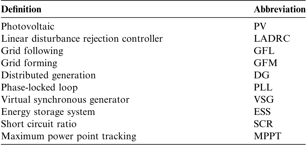
DefinitionAbbreviation PhotovoltaicPV Linear disturbance rejection controllerLADRC Grid followingGFL Grid formingGFM Distributed generationDG Phase-locked loopPLL Virtual synchronous generatorVSG Energy storage systemESS Short circuit ratioSCR Maximum power point trackingMPPT
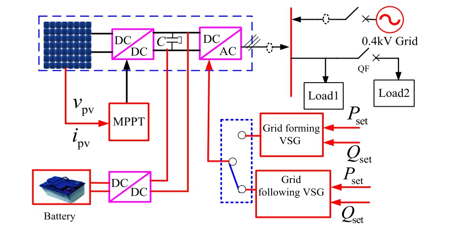
Fig.1.Basic structure diagram of VSG dual-mode adaptive switching for PV energy storage microgrid.
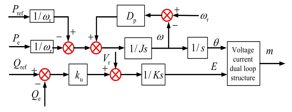
Fig.2.Basic principle block diagram of GFM VSG control.
The specific expressions of Gpwm, GPV, GPQ, G1, GPI, , and ZL are as follows:
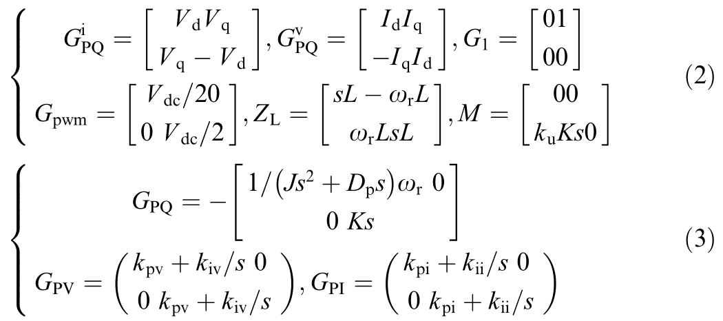
where Vd and Vq represent the steady-state values of the GFM VSG output voltage (dq axis components); Id and Iq denote the steady-state values of GFM VSG output current(dq axis components);Vdc represents the DC bus voltage value; L denotes the filtering inductor; kpv and kiv represent the proportional integral coefficients of the voltage loop PI controller; and kpv and kiv represent the proportional integral coefficients of the current loop PI controller, respectively.
2) Impedance model of GFL VSG inverter
Fig.3 presents a block diagram that shows the basic principle of GFL VSG control.
The GFL VSG impedance model is given by [24,25]

where  and
and  represent the effects of PLL dynamics on the output current, port voltage, and duty cycle,respectively; Gid denotes the transfer function between the inverter output duty cycle and output current iL; ZL is the open-loop impedance of the inverter; Gdec is the decoupling matrix of the current inner loop; Gdel is the delay matrix; GPI is the current inner loop PI controller;
 represents the transformation matrix ([ΔPe,ΔQe] changes to [Δidref, Δiqref]).
The specific expressions of  , Gid, ZL, Gdec,Gdel, and GPI are given by
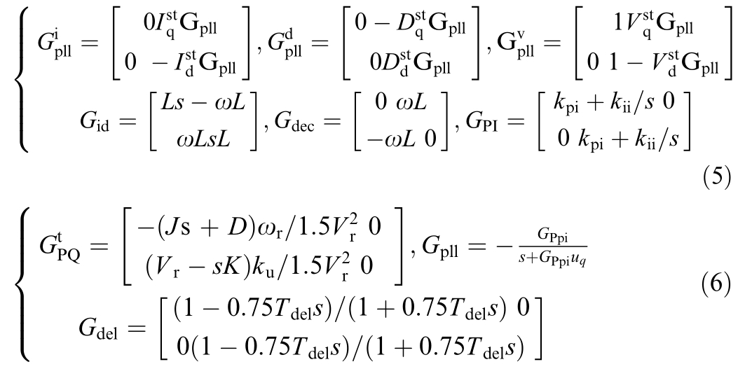
where  and
and  represent the steady-state values of the GFL VSG output voltage (dq axis components);
  and
and represent the steady-state values of the GFL VSG output current (dq axis components);
  and
and  denote the steady-state values of the GFL VSG output duty cycle(dq axis component); Gpll represents the transfer function of the PLL; GPpi denotes the PLL PI controller; uq is the q-axis voltage of the power grid.Tdel = e-Ts, where T is the switching period.
1.2 PV DC side impedance model
1) DC/DC boost circuit
Fig.4 illustrates the control principle diagram of the PV DC/DC boost circuit.In this figure, L1 denotes the inductance, and idc denotes the output current of the DC/DC boost circuit.vmp is the maximum power point tracking(MPPT)output voltage,and Gpv is the PI controller(kpb+-kpi/s).
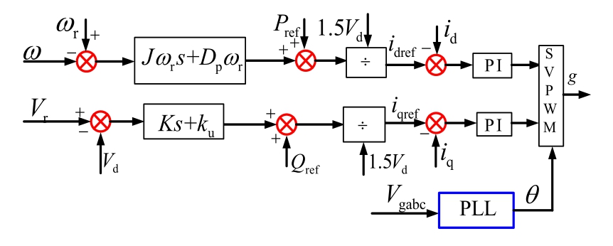
Fig.3.Basic principle block diagram of GFL VSG control.
PV array output current is given by [13]
where e denotes the electronic charge constant(1.6021710 19 C); k denotes the Boltzmann constant;Io represents the saturation current; Iscr represents the short-circuit current; np denotes the parallel PV modules number;nm represents the number of parallel PV modules;and T is the actual temperature.Linearizing (7) gives,
where kpvenpIo 1 eV pv0 nmkT nmkT, V pv0 is the steady-state value of the PV output voltage.
The maximum power point, characterized by ipv, and vmp satisfy the condition given in (9):
Substituting (8) into (9) and linearizing it yields

where Ipv0 represents the PV output steady-state current value, and Vmp0 represents the steady-state value of the PV maximum power tracking output voltage.
According to Fig.4,the linearized model of the DC/DC boost circuit can be expressed as

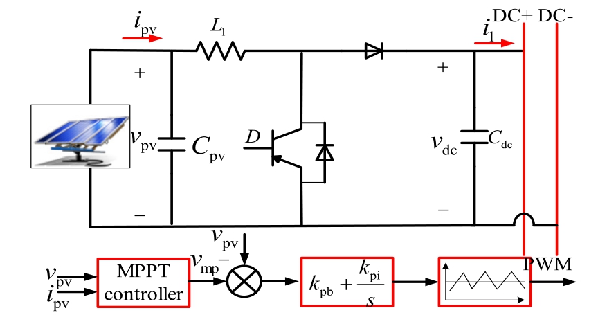
Fig.4.Control principle block diagram of the PV DC/DC boost circuit.
where Cpv represents the filtering capacitor on the PV side;D represents the duty cycle of DC/DC boost circuit switch driver; Cdc represents the filtering capacitor on DC bus side;Vdc0 denotes the DC bus output steady-state voltage;IL0 represents the flow through L1 steady-state current; Δi is the small disturbance current flowing into the ESS; and Δidc is the small disturbance current flowing into the DC bus.
By simplifying (11), we obtain (12)
where

2) Buck boost circuit of energy storage system
Fig.5 illustrates the control principle block diagram of the energy storage system (ESS).In Fig.5, Lb denotes the system inductance;Ub is the battery voltage; ib represents the battery current; i represents the ESS output current;vdc represents the DC bus voltage;Gbpv denotes the voltage PI controller; and Gbpi is the current PI controller.
The ESS output current is given as,
where d12 is the duty cycle of the ESS switch driver.
By linearizing(13),the following expression is obtained:
where Ib0 denotes the steady-state output current of the battery.
According to Fig.5, the expression for Δd12 is:
The DC bus energy expression is
where C is the capacitance of the DC bus capacitor; ΔPpv is the small disturbance of the active power output from the PV; ΔPsoc is the small disturbance amount of active power during ESS charging and discharging; and ΔPinv represents the small disturbance of the active power flowing into the inverter.
Equation (17) is derived from (16):
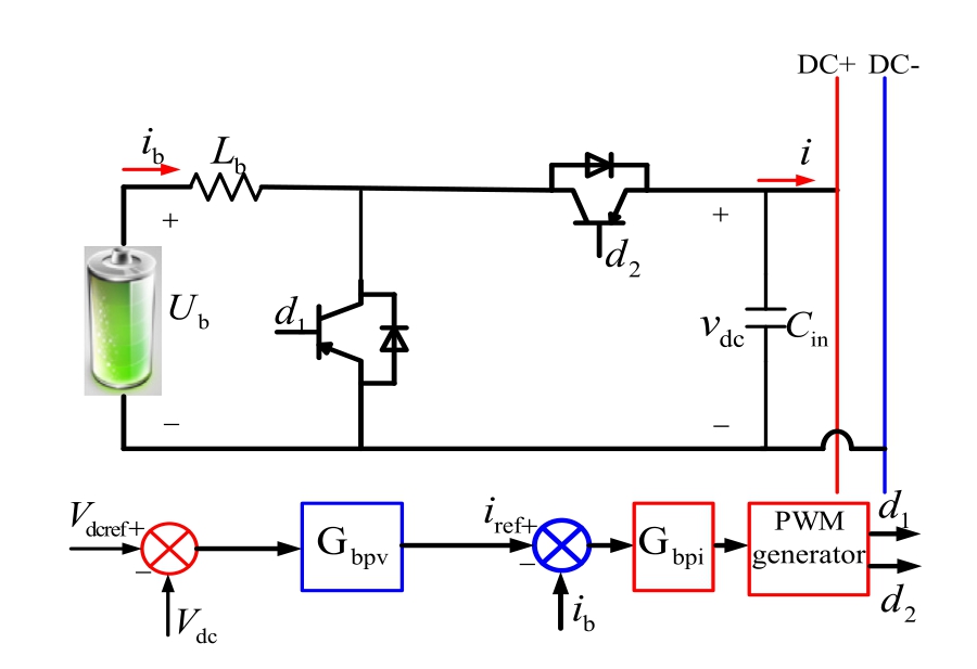
Fig.5.Battery ESS charging and discharging circuit.
Subsequently, (18) is obtained from (17)
The power expression for both ends of the DC bus can be expressed as
where idc represents the current flowing into the DC bus.
The expression for ΔPin can be obtained from (19) as follows:
where Idc represents the steady-state current flowing into the DC bus; and Vdcref represents the steady-state voltage value of the DC bus.
Battery current ib small signal expression is
According to(14),(15),and(21),the expression for Δib is

where
Substituting (15) and (22) into (14) yields
where
From (12) and (23), the equivalent impedance expression of the PV VSG system is derived as:
Finally, the equivalent impedance model expressions for the GFM VSG and GFL VSG systems, considering PV and energy storage, can be obtained from (1), (4),and (24), respectively:


2 Grid-connected stability analysis of PV VSG system
2.1 Grid-connected stability analysis of PV GFM VSG
Fig.6 presents the J, D, SCR, light intensity, and DC bus capacitance variation Bode diagrams.
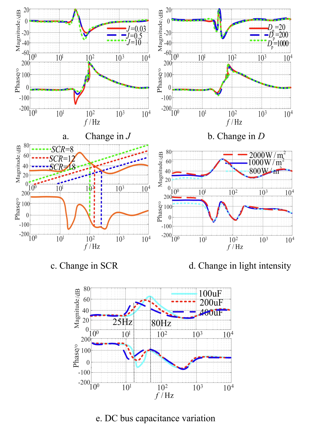
Fig.6.GFM PV impedance Bode diagram.
Fig.6a shows that insufficient system inertia leads to negative resistance behavior near 50 Hz.As J increases,the amplitude of the system impedance moves away from the negative resistance region, whereas the overall impedance profile remains relatively stable.Fig.6b shows that with an increase in D,the amplitude and phase angle of the system impedance remain almost unchanged,and have little impact on the system impedance.Fig.6c shows that under a weak power grid with SCR = 8, the phase angle of the equivalent PV GFM VSG system remains outside the negative resistance region, indicating that the system remains stable.When SCR changes from 6 to 12 (strong grid), the equivalent impedance phase angle of the PV GFM VSG system begins to enter the negative resistance region, leading to resonance.When the SCR further increases to 18, representing an even stronger power grid,the system equivalent impedance phase angle begins to enter the negative resistance region more deeply, leading to a more pronounced and severe system resonance.As the SCR increases (SCR enters into a strong power grid),the system gradually becomes unstable.This suggests that a strong power grid is not necessarily beneficial for the stable operation of the PV GFM VSG system.Fig.6d demonstrates that variations in light intensity, impedance amplitude, and phase angle result in slight changes in the low-frequency range, yet the system can still maintain stability.Changes in light intensity have a relatively minor impact on system stability.Fig.6e shows that as C increases, the system bandwidth at the resonance peak intersection decreases from approximately 80-25 Hz.This indicates that a smaller ripple will be allowed to pass through the front-end circuit with larger capacitors, and a smaller ripple will appear at the DC bus voltage.
2.2 Grid-connected stability analysis of PV GFL VSG system
Fig.7 presents the Bode diagrams of variations in J,D,PLL bandwidth fpll, SCR, light intensity, and DC bus capacitance.
Fig.7a shows that when the J value of GFL VSG is too small, a significant negative resistance component appears near 50 Hz.As J increases, the amplitude of the system impedance shifts away from the negative resistance region and remains largely unchanged.Fig.7b demonstrates that with an increase in D,both the amplitude and phase angle of system impedance exhibit minimal variation and have little impact on system impedance.Fig.7c shows that with an increase in fpll, the phase angle of the impedance gradually approaches the negative resistance region, making the system more susceptible to resonance.The PLL bandwidth employed in this study is fpll = 30 Hz.Fig.7d indicates that when SCR(SCR=6)is a weak power grid,the equivalent impedance phase angle of the PV GFL VSG system enters the negative resistance region, and the system will resonate.As the SCR increases from 6 to 12(strong grid), the equivalent impedance phase angle of the system remains outside the negative resistance region,and the system remains stable.With a further increase in SCR to 20, the impedance phase angle shifts even farther from the negative resistance region,thereby enhancing system stability.These observations indicate that increasing grid strength has a stabilizing effect on the PV GFL VSG system.Fig.7e shows that variations in light intensity cause only slight changes in the output impedance,and the system remains stable.Changes in light intensity have a relatively small impact on system stability.Fig.7f demonstrates that as C increases, the system bandwidth at the resonance peak intersection decreases from approximately 75-50 Hz.This suggests that a smaller ripple will be allowed to pass through the front-end circuit with larger capacitors, giving rise to a smaller ripple at the DC bus voltage.
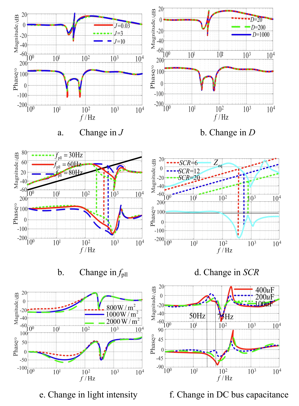
Fig.7.GFL PV impedance bode diagram.
3 Online impedance identification and smooth switching method
3.1 Online impedance identification method
A commonly used technique for online impedance identification is the harmonic injection method [18-20,26,27],in which a harmonic voltage or current is injected and the voltage and current of a certain frequency band are then extracted to obtain the online impedance value of the power grid.By injecting high-frequency signals, the signal-to-noise ratio is improved, thereby enhancing the accuracy of impedance identification of the power grid.However, the injection of high-frequency disturbance signals will exacerbate the risk of system instability.To address this, [28,29] proposed an online impedance identification method based on power angle measurement using Kalman filtering.Although this approach is affected by the degree of system noise interference, the larger the covariance of system measurement noise, the better the Kalman filtering effect. [30,31] introduced an online impedance identification method for power grids using the least squares estimation method.The least squares recursive estimation method involves a high computational load and is therefore less suitable for practical implementation in embedded systems.To improve the accuracy of impedance identification, this study proposes an online identification method based on the screening of voltage fluctuation data for the Thevenin equivalent impedance.
Fig.8 illustrates the grid connection point voltage current phasor diagram.In Fig.8, Ug represents the equivalent voltage of the Thevenin; Us and Is represent the voltage and current at grid connection point, respectively;Zg represents the equivalent impedance of Thevenin; Rg and Xg represent the equivalent impedance resistance and inductance of the Thevenin, respectively; θ denotes the phase angle between voltage and current at the grid connection point; and φ denotes the angle between grid connection point current and IsZg.
Based on Fig.8,the expression for grid voltage is given as,

where
By selecting three different sets of measurement values and substituting them into (27), we obtain:

Equation (28) can be expressed in matrix form as:
where

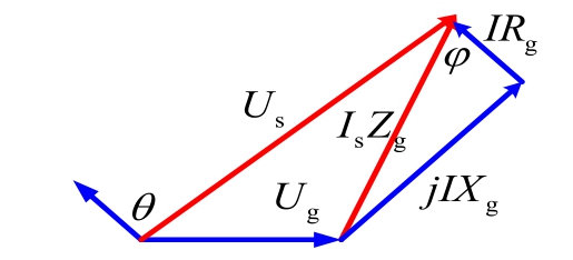
Fig.8.Voltage-current phasor diagram at the grid connection point.
According to 29, a linear relationship between the unknown parameters R and X can be established by measuring any three distinct operating points.For any set {A,B, C}i, substituting {A, B, C} into (29) yields:
According to 30,the accuracy of grid impedance identification is influenced by fluctuations in power and voltage.In general, power output exhibits relatively minor variations under given active and reactive power settings.Therefore, voltage fluctuations are the primary factor affecting the accuracy of impedance identification.Thus,it is necessary to remove those with larger voltage fluctuations from the sampled data.An outlier clustering detection algorithm was applied for sample data screening based on the voltage standard deviation coefficient.
We define sample mean E, variance D, and standard deviation coefficient ρv as follows:

Then, we set the voltage fluctuation threshold k(0 k ρv).The data used for identifying the equivalent parameters of Thevenin must satisfy (32).
The voltage fluctuation rate is expressed as
Fig.9 presents the probability plot of voltage fluctuation at a distributed photovoltaic grid connection point.
Fig.9 shows that the grid-connected voltage has a high probability of fluctuating around 0.3%,whereas the power fluctuation rate is mostly distributed within 0.9%.The correlation coefficient of voltage fluctuation rate is approximately 0.0105, and the correlation coefficient of power fluctuation rate is approximately 0.0095.These values indicate no significant correlation between voltage and active power, allowing the selection of data with smaller voltage and active power fluctuations.
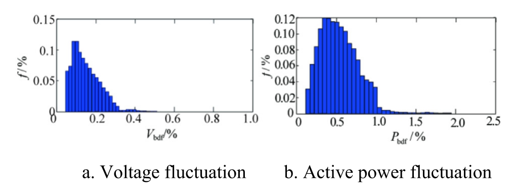
Fig.9.Probability diagram of voltage fluctuation at the grid connection point.
Then,we set the k values to 0 7ρv and 0 5ρv and filtered the voltage fluctuation data according to(26).Fig.10 illustrates the data point graphs before and after filtering.
Fig.10 shows that the measurement data points generally follow a linear trend.Leveraging this linearity,abnormal data caused by measurement errors and noise can be effectively identified and removed.As the voltage fluctuation at the measurement point is not directly observable,a voltage fluctuation threshold is set based on (27).The outlier clustering detection algorithm is then applied to select data with low voltage fluctuation,using the standard deviation coefficient, and to remove abnormal numerical data based on the linear distribution of measurement data points.The filtered data is employed for grid-side Thevenin equivalent impedance identification, thereby enhancing the identification accuracy.
Fig.11 presents the impedance parameters identification results using filtered data (N = 40).The average values of grid reactance and resistance are approximately 14.41 Ω and 1.72 Ω, respectively, with the errors of 0.6%and 14.67% compared to the actual values (14.5 Ω and 1.5 Ω).According to(30),the resistance value is influenced not only by voltage fluctuations but also by active power fluctuations.Compared to the inductance value, its value fluctuation range is larger, resulting in a higher relative error in impedance identification.Because the resistance value is considerably smaller than the reactance,the resulting error has a limited impact on the overall impedance modulus identification accuracy.
Fig.12 compares the results of screening voltage fluctuation data for online identification of Thevenin impedance and identification based on the least squares method.Fig.12 also demonstrates that the online identification method of Thevenin impedance based on voltage fluctuation data yields higher identification accuracy than the least squares method.
Power grid strength is characterized by the short circuit ratio (SCR), which is commonly used to classify power grids as strong, weak, or extremely weak.SCR range values of strong and weak power grids differ according to various reference definitions.In this study,a weak power grid is defined as having 2 SCR <10,whereas a strong power grid corresponds to SCR 10[32].An adaptive switching SCR critical value between dual-mode VSG is SCR = 10.When SCR is greater than or equal to 10, PV operates in grid-following mode.When SCR is less than 10, PV switches to grid-forming mode.
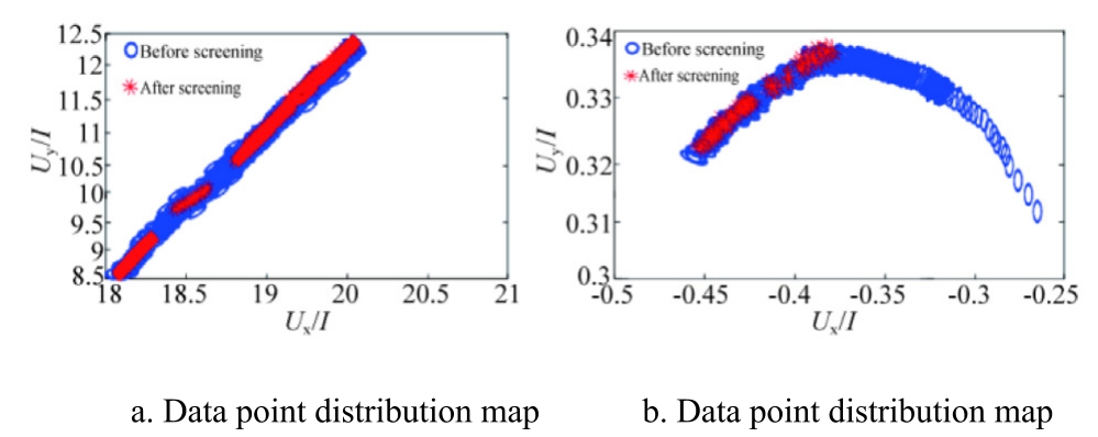
Fig.10.Distribution of data before and after filtering.
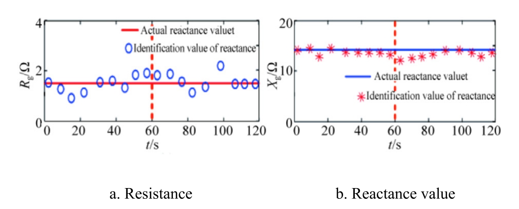
Fig.11.Impedance identification results after filtering voltage fluctuation data.
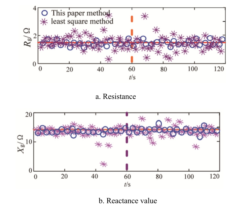
Fig.12.Impedance online identification results.
3.2 GFM-GFL smooth switching method based on current inner loop compensation
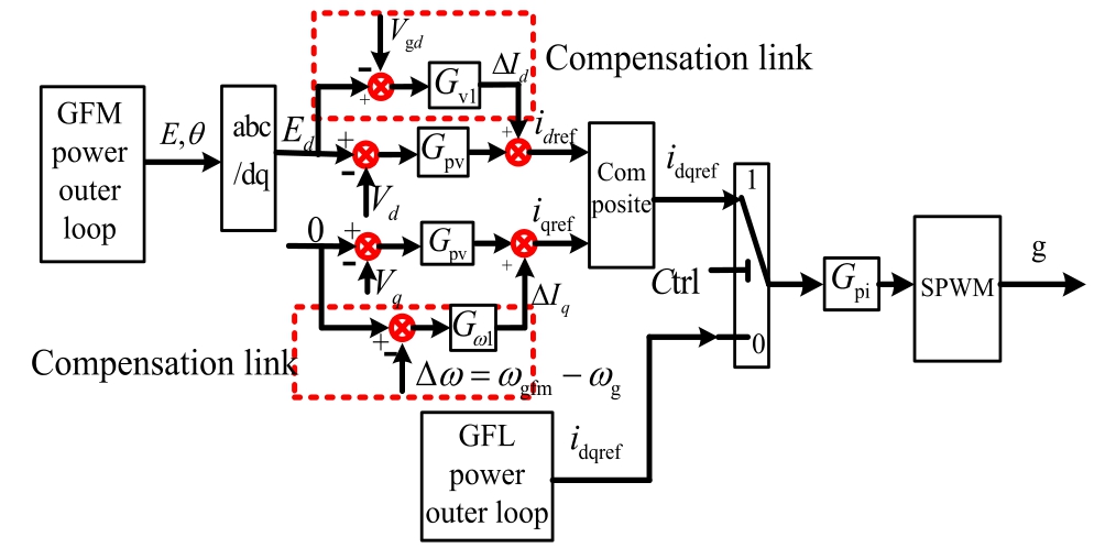
Fig.13.Block diagram of the resonance suppression control principle for the smooth switching of distributed photovoltaic.
To ensure the stable operation of distributed photovoltaic systems without resonance during transitions between strong and weak power grids, smooth switching between GFL and GFM VSG control is necessary.Fig.13 shows the smooth switching control principal block diagram for a distributed photovoltaic system.When the power grid operates as a strong grid,the photovoltaic energy storage system adopts GFL VSG control for grid-connected operation and utilizes a PLL to maintain synchronization with the grid.When power grid strength shifts from strong to weak, the system switches from GFL VSG control to GFM VSG control.To eliminate switching disturbances, the error between the output voltage Ed of the GFM VSG and the grid voltage d-axis component of the grid voltage is processed by a PI controller to generate a d-axis disturbance error current.This current is compensated into the d-axis reference current to support system regulation and eliminate disturbance errors, thereby achieving voltage amplitude synchronization.For the q-axis component where Eq = 0, the error between zero and angular velocity change (the deviation between GFM VSG angular velocity ωgfl and GFL VSG angular velocity ωg) is processed through a PI controller to generate a q-axis disturbance current,which is compensated into the q-axis reference current to support system regulation and eliminate disturbance errors, thereby achieving consistency in voltage phase angle.When the power grid intensity changes from weak to strong, the PV energy storage system must switch from GFM VSG control to GFL VSG control.Because the GFM VSG system remains synchronized with GFL VSG through the current inner loop compensation,it can be smoothly transitioned to GFL VSG control, ultimately achieving smooth switching control of distributed photovoltaic under variations in grid strength and effectively suppressing system resonance.
1) Strong power grid changes to weak power grid
When the system detects a change in grid impedance from strong to weak, the GFL VSG distributed photovoltaic system switches from GFL to GFM operation.Fig.14 shows the system simulation waveform.
Fig.14 shows that at t = 0.4 s, the power grid transitions from strong to weak.If the distributed photovoltaic system operates under grid-following control,system resonance occurs.In contrast, applying the smooth switching method results in a smooth output current waveform,effectively suppressing resonance.
2) Weak power grid changes to a strong power grid
When the system detects a change in grid impedance from weak to strong, the GFM VSG distributed photovoltaic system switches from GFM to GFL operation.Fig.15 presents the system simulation waveform.
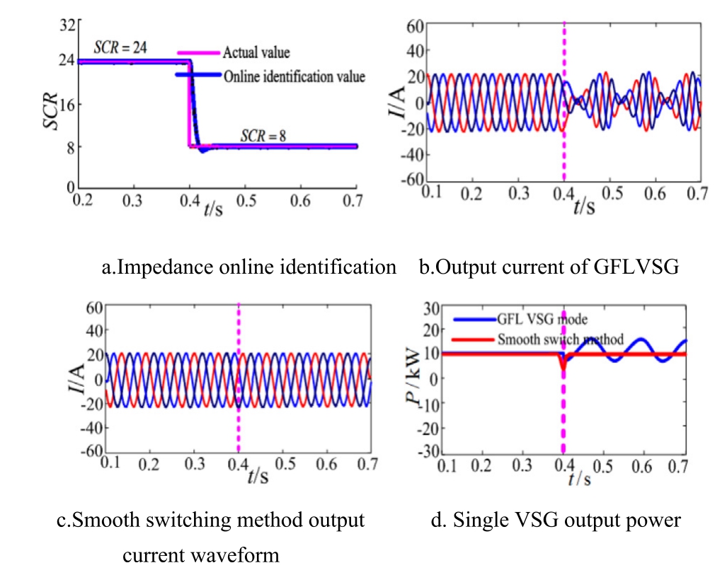
Fig.14.Simulation waveform of smooth switching resonance suppression for a single VSG.
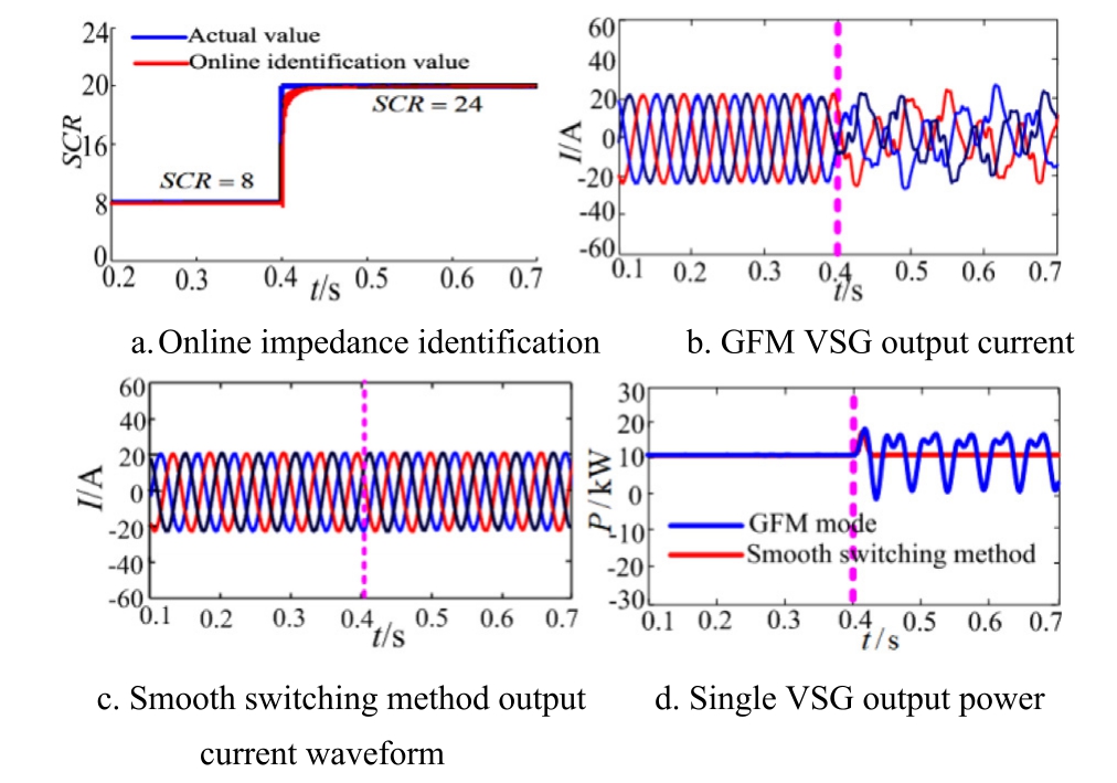
Fig.15.Simulation waveform of single VSG smooth switching resonance suppression.
Fig.15 shows that when SCR transitions from weak to strong,a distributed photovoltaic system using only GFM control experiences resonance.If the photovoltaic system is equipped with dual-mode control and capable of smooth switching, the output current waveform remains smooth,effectively suppressing resonance under strong power grid conditions.
4 Stability analysis and simulation testing of multi-machine parallel PV VSG grid connection
4.1 Stability analysis of multi-machine parallel distributed photovoltaic grid connection
A hybrid system consists of m current sources and n voltage sources, with voltage and current values of Vref and Iref,respectively,and Zc1=Zc2=Zcm=Zgfl,Zv1=-Zv2=Zvn=Zgfm.Fig.16 presents the equivalent circuit schematic of a hybrid system integrating GFM and GFL sources.
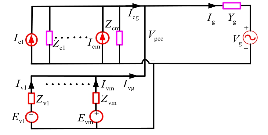
Fig.16.Equivalent circuit schematic of PV hybrid system.
Based on Fig.16, the expression of Vpcc is expressed as
The stability of the heterogeneous hybrid system is determined by the characteristic equation expressed in(35).
Using the single input single output (SISO) equivalent impedance transformation method proposed in [33], the system impedance is converted into a SISO equivalent form, as presented in (36).

where
According to the positive network damping criterion,if the real part at the zero-crossing point of the imaginary part of the sum of the equivalent impedance and the equivalent impedance of the power grid is greater than 0, the system has a positive damping and is stable; otherwise, it is unstable.
When SCR = 20, ①m = 1 (increasing the number of n);②n=1(increasing the number of m).Fig.17 presents the imaginary and real part curves of the sum of the equivalent impedance.
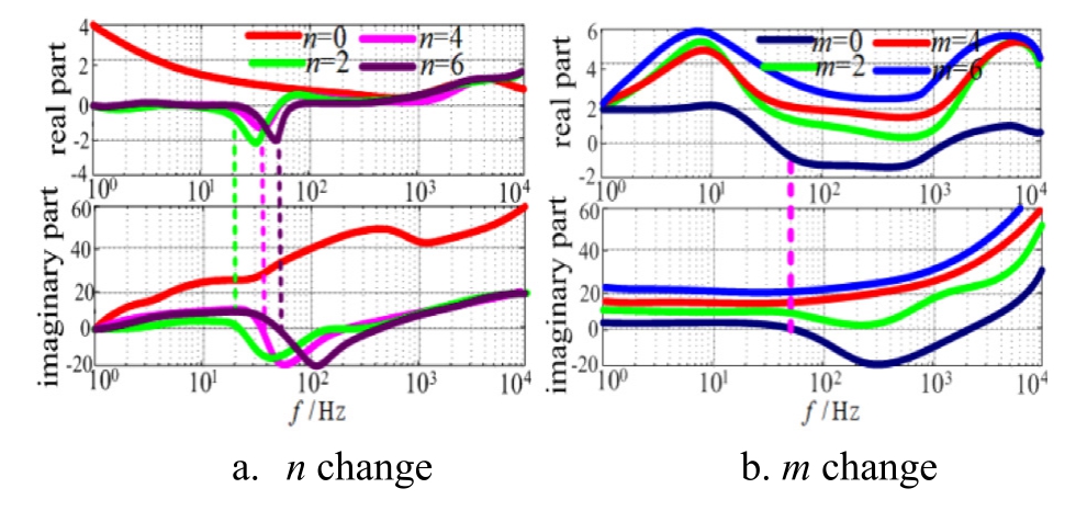
Fig.17.Real and imaginary parts of the summed equivalent impedance for varying GFM numbers.
Fig.17a illustrates that under a strong power grid,increasing the number of GFM inverters introduces negative damping in the system,with larger numbers worsening the effect,which is detrimental to system stability.Fig.17b indicates that increasing m in strong power grid conditions maintains positive damping characteristics, supporting system stability.
When SCR=8,①m=1(increasing the number of n);②n=1(increasing the number of m).Fig.18 presents the imaginary and real part curves of the summed equivalent impedance.
Fig.18a shows that increasing the number of GFM inverters in weak power grids still results in positive system damping characteristics, which enhances system stability.Fig.18b demonstrates that,in weak current grids,increasing the number of GFL inverters introduces negative damping, and as m increases, the negative damping effect intensifies, which is detrimental to system stability.
4.2 Simulation verification
A simulation model of the smooth switching resonance suppression method for a distributed photovoltaic multimachine parallel VSG system is established for testing.Table 2 presents the system parameters.
A.Weak power grid changes to a strong power grid
1) Heterogeneous parallel system
Multiple heterogeneous parallel systems: two distributed generations (DG), i.e., DG1 and DG2, operate in the GFM model, and one DG (DG3) operates in the GFL model.When SCR changes from weak to strong grid at t = 0.4 s, DG1 and DG2 adaptively switch from GFM to GFL operation.Fig.19 presents the system simulation waveform.
Fig.19 illustrates that in a parallel system consisting of two GFM DGs and one GFL DG, when the SCR transitions from weak to strong,the system output always maintains resonance.If the two GFM DGs are adaptively switched to GFL operation at 0.4 s, the heterogeneous three-DG system outputs stable current, effectively suppressing system resonance.
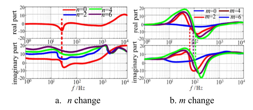
Fig.18.Real and imaginary parts of the summed equivalent impedance for different numbers of GFM.
Table 2 System parameters.
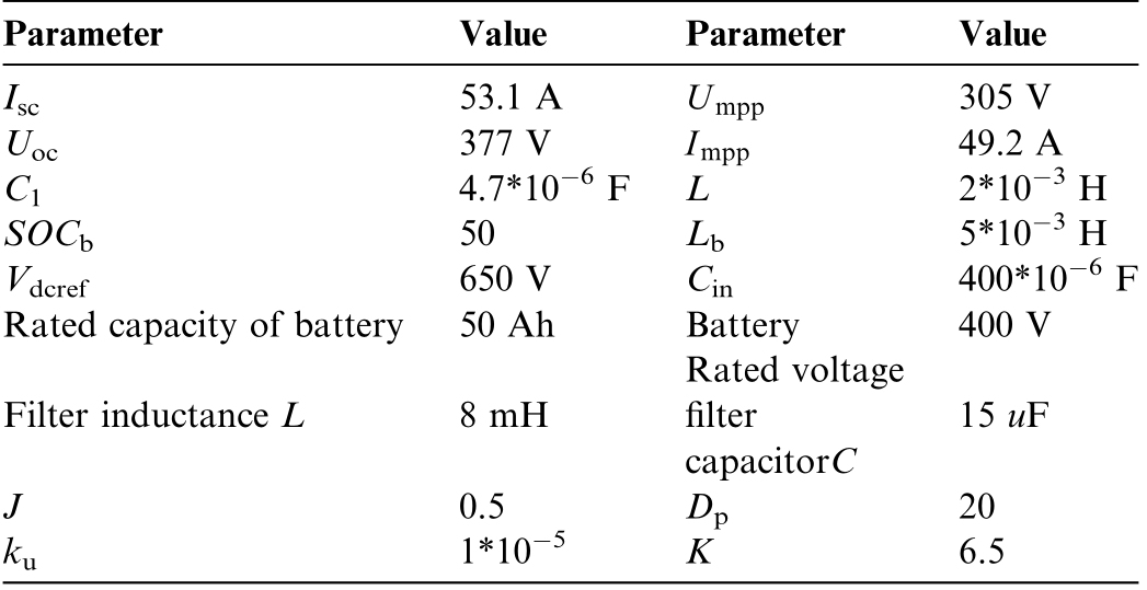
ParameterValueParameterValue Isc53.1 AUmpp305 V Uoc377 VImpp49.2 A C14.7*10 6 FL2*10 3 H SOCb50Lb5*10 3 H Vdcref650 VCin400*10 6 F Rated capacity of battery50 AhBattery Rated voltage 400 V Filter inductance L8 mHfilter capacitorC 15 uF J 0.5Dp20 ku1*10 5K6.5
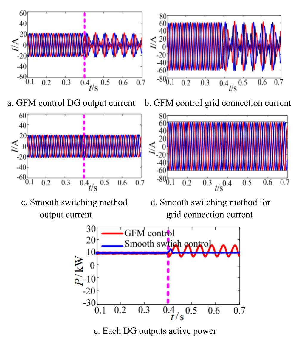
Fig.19.Simulation waveform of a heterogeneous parallel system.
2) Isomorphic parallel system
Multi-machine parallel isomorphic system: three DGs operate in the GFM mode.When the SCR increases from weak to strong at t=0.4 s,all three DGs adaptively switch from GFM to GFL operation.Fig.20 presents the system simulation waveform.
Fig.20 demonstrates that in a homogeneous parallel system composed of three GFM DGs, when the grid strength increases from weak to strong at t=0.4 s,the system output transitions from stable to resonant.If the three GFM DGs adaptively switch to GFL operation at t = 0.4 s, the isomorphic parallel system outputs a stable current, and system resonance is effectively suppressed.
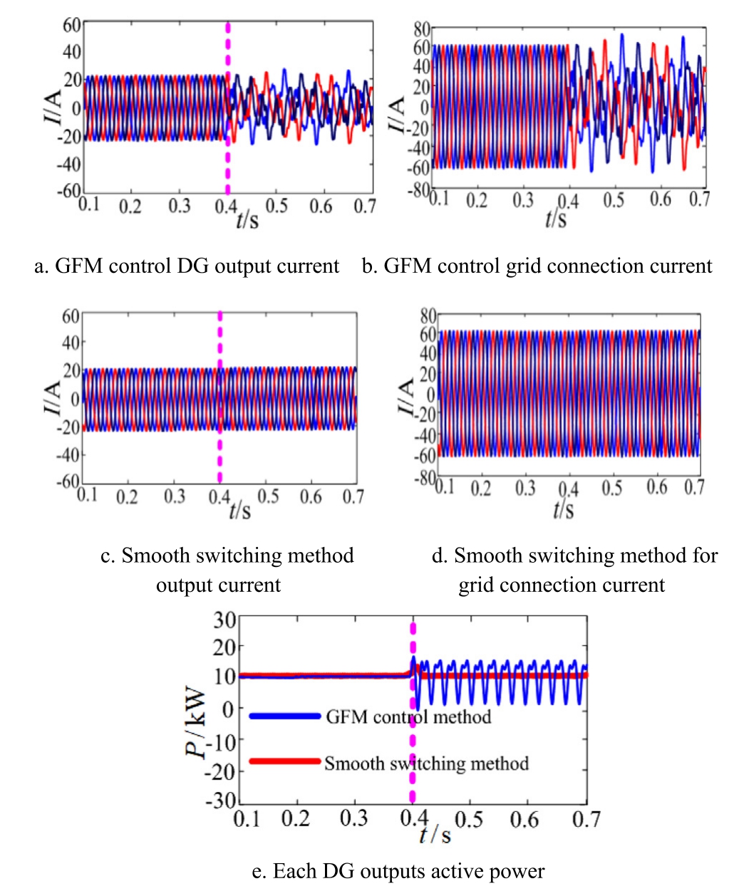
Fig.20.Simulation waveform of an isomorphic parallel system.
B.Strong power grid changes to weak power grid
1) Heterogeneous parallel system
Multi-machine heterogeneous parallel system:two DGs(DG1, DG2) operate in GFL mode, and one DG (DG3)operates in GFM mode.When the SCR changes from strong to weak grid, DG1 and DG2 adaptively switch from GFL to GFM mode.Fig.21 shows the system simulation waveform.
Fig.21 shows that in a parallel system with two GFL DGs and one GFM DG, the system output exhibits resonance when the grid strength transitions from strong to weak at t=0.4 s.If two GFL DGs are adaptively switched to GFM mode,three DGs in a heterogeneous parallel system produce stable current and suppress resonance.
2) Isomorphic parallel system
Multi-machine parallel isomorphic system: three DGs(DG1, DG2, DG3) operate in the GFL mode.When SCR changes from strong to weak grid at t = 0.4 s, the three DGs adaptively switch from GFL to GFM operation.Fig.22 presents the system simulation waveform.
Fig.22 demonstrates that in a homogeneous parallel system of three GFL DGs, when SCR decreases from strong to weak grid at 0.4 s, the system output transitions from stable to resonant.If all three GFL DGs adaptively switch to GFM at 0.4 s, the isomorphic parallel system of the three DGs will output a stable current,and system resonance will be suppressed.
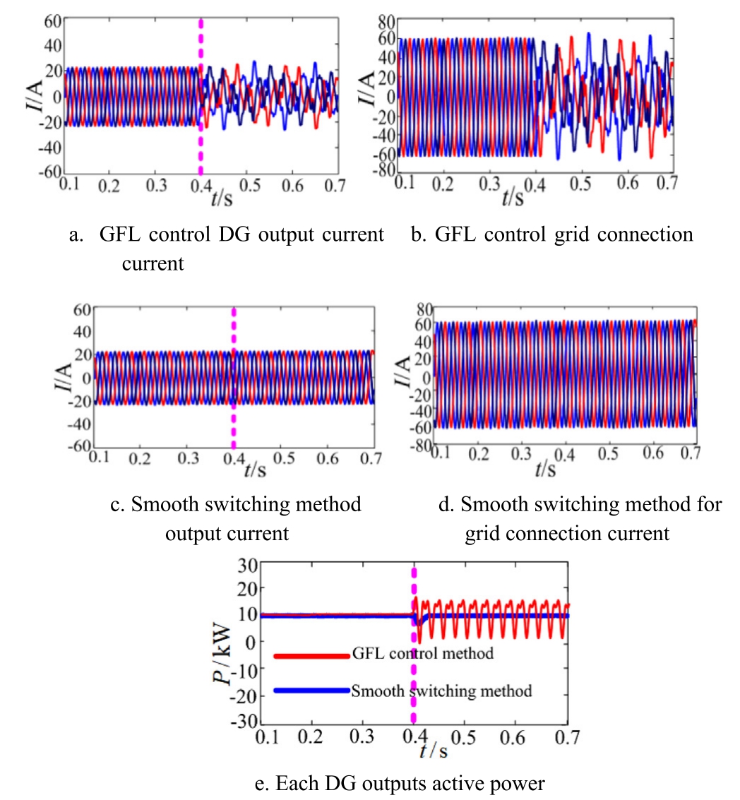
Fig.21.Simulation waveform of a heterogeneous parallel system.
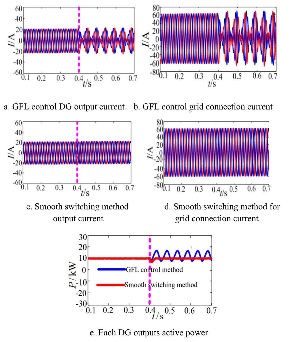
Fig.22.Simulation waveform of an isomorphic parallel system.
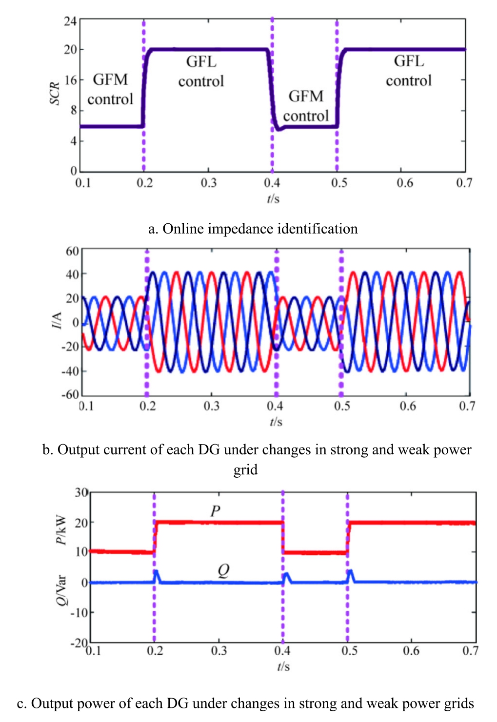
Fig.23.Simulation waveform of adaptive smooth switching gridconnected control for distributed photovoltaic under strong and weak power grids.
Distributed photovoltaic adopts a smooth switching and grid connection control strategy that integrates with the grid and constructs the grid.The simulation waveform demonstrating adaptive switching and grid connection under varying grid strength is shown in Fig.23.The reference active power ratio between GFM and GFL is set to 1:2.
Fig.23 shows that when the system detects changes in grid strength between strong and weak conditions, the GFL-GFM fusion control strategy enables smooth switching and adaptive grid connection regulation, effectively suppressing system resonance.
5 Conclusion
To ensure the stable operation of a multi-machine parallel PV energy storage microgrid under varying grid strength without inducing resonance, this study proposed a distributed PV parallel smooth switching resonance suppression control strategy.The main conclusions are:
1) PV energy storage,GFM VSG,and GFL VSG have complementary characteristics.GFL VSG performs well in strong power grids, whereas GFM VSG is better suited for weak power grids.
2) The online identification method of Thevenin equivalent impedance based on voltage fluctuation data achieves higher impedance identification accuracy than the least squares method.
3) The smooth switching resonance suppression method for distributed photovoltaic VSG systems provides stronger resonance suppression than a single GFL/GFM control method, enabling distributed photovoltaic systems to adapt to grid strength variations and maintain stable, resonance-free operation.
CRediT authorship contribution statement
Zuobin Zhu: Software, Investigation, Writing - review& editing, Methodology, Writing - original draft.Shumin Sun:Supervision,Funding acquisition,Project administration.Yueming Ding: Visualization, Validation, Investigation, Resources.
Declaration of competing interest
The authors declare the following financial interests/personal relationships which may be considered as potential competing interests:Shumin Sun is currently employed by State Grid Shandong Electric Power Company Electric Power Science Research Institute, and Yueming Ding is currently employed by State Grid Shandong Electric Power Company Rizhao Power Supply Company.
Acknowledgments
This work was supported by National Key Research and Development Technology Project program(SQ2022YFB2400136).
References
-
[1]
S.H.Shen, T.Z.Fang, Y.F.Zhang, A high-bandwidth digitalcontrol LCL-type grid-tied inverter and resonance-suppressing technique for improving the robustness of grid-connected system,Trans.China Electrotech.Soc.37 (21) (2022) 5548-5561. [百度学术]
-
[2]
C.M.Tu, K.X.Zou, J.Y.Gao, et al., Stability analysis of gridconnected inverter under PQ power control based on asymmetric positive-negative-feedback effects, Trans.China Electrotech.Soc.37 (21) (2022) 496-509. [百度学术]
-
[3]
Y.T.Li, Y.J.Gu, T.C.Green, Revisiting grid-forming and gridfollowing inverters:a duality theory,IEEE Trans.Pow.Syst.37(6)(2022) 4541-4554. [百度学术]
-
[4]
X.R.Liu, H.N.Sun, R.Wang, et al., Stability enhancement method for grid-connected inverters under weak grid:an improved feedforward control considering phase-locked loop, IET Electr.Pow.Appl.16 (9) (2022) 1004-1016. [百度学术]
-
[5]
M.Yang, Z.Yang, Y.L.Li, et al., Impedance remodeling control strategy of grid-connected inverter based on feedforward voltage under weak grid, Trans.China Electrotech.Soc.39 (08) (2024)2553-2566. [百度学术]
-
[6]
H.Nian, B.Hu, Y.Y.Xu, et al., Analysis and reshaping on impedance characteristic of DFIG system based on symmetrical PLL, IEEE Trans.Pow.Electron.35 (11) (2020) 11720-11730. [百度学术]
-
[7]
D.S.Yang,X.F.Wang,F.C.Liu,et al.,Symmetrical PLL for SISO impedance modeling and enhanced stability in weak grids, IEEE Trans.Pow.Electron.35 (2) (2020) 1473-1483. [百度学术]
-
[8]
M.Yang, Z.Yang, Y.L.Li, et al., A phase-locked loop design method based on impedance remodeling of grid-connected inverter under high permeability, Trans.China Electrotech.Soc.39 (2)(2024) 554-566. [百度学术]
-
[9]
Z.Wang,P.Cheng,L.M.Jia,Single-input single-output impedance modeling and analysis of three-phase grid-tied converter based on symmetric control, Trans.China Electrotech.Soc.39 (06) (2024)1777-1791. [百度学术]
-
[10]
C.Liu, M.C.Zhao, H.J.Wang, et al., Modelling of sequence impedance of renewable energy synchronous generator and its suppression effect on broadband oscillation, Pow.Syst.Technol.48 (09) (2024) 3595-3603. [百度学术]
-
[11]
W.J.Ma, Y.P.Guan, B.Zhang, Active disturbance rejection control based control strategy for virtual synchronous generators,IEEE Trans.Energy Convers.35 (4) (2020) 1747-1761. [百度学术]
-
[12]
Y.Lei, G.H.Li, W.S.Wang, et al., Impedance modeling and characteristics analysis of photovoltaic generation considering photovoltaic array, Proc.CSEE 44 (13) (2024) 5122-5135. [百度学术]
-
[13]
E.S.Zhao, Y.Han, X.Y.Lin, et al., Impedance characteristics investigation and oscillation stability analysis for two-stage PV inverter under weak grid condition, Electr.Pow.Syst.Res.209(2022) 108053. [百度学术]
-
[14]
D.Y.Zeng, J.Yao, T.Zhang, et al., Research on frequency smallsignal stability analysis of multi-parallel virtual synchronous generator-based system,Proc.CSEE 40(7)(2020)2048-2061,2385. [百度学术]
-
[15]
S.K.Wang, Z.Liu, J.J.Liu, et al., Small-signal modeling and stability prediction of parallel droop-controlled inverters based on terminal characteristics of individual inverters, IEEE Trans.Pow.Electron.35 (1) (2019) 1045-1063. [百度学术]
-
[16]
Y.Wang,A.J.Gao,N.Hu,et al., Resonance suppression strategy for multi-parallel grid-connected inverters, South.Pow.Syst.Technol.16 (5) (2022) 87-96. [百度学术]
-
[17]
Z.L.Wang, Y.D.Chen, W.H.Wu, et al., Adaptive harmonic impedance reshaping current-sharing control method of parallel VSGs with different capacities and its stability analysis, Proc.CSEE 41 (24) (2021) 8571-8585. [百度学术]
-
[18]
M.Li,X.Zhang,Z.X.Guo,et al.,Impedance adaptive dual-mode control of grid-connected inverters with large fluctuation of SCR and its stability analysis based on D-partition method,IEEE Trans.Pow.Electron.36 (12) (2021) 14420-14435. [百度学术]
-
[19]
M.Li, X.Zhang, Y.Yang, et al., The grid impedance adaptation dual mode control strategy in weak grid, in: Proceedings of 2018 International Power Electronics Conference (IPEC-Niigata 2018 -ECCE Asia), IEEE, Niigata, Japan, 2018, pp.2973-2979. [百度学术]
-
[20]
L.Ming, Z.Xing, Z.Wei, A novel stability improvement strategy for a multi-inverter system in a weak grid utilizing dual-mode control, Energies 11 (8) (2018) 2144. [百度学术]
-
[21]
Z.X.Liu, L.Qin, Y.Y.Zhou, et al., An adaptive multi-mode switching control strategy to improve the stability of virtual synchronous generator with wide power grid strengths variation,IET Gener.Transm.Distrib.17 (2) (2023) 307-323. [百度学术]
-
[22]
M.Li, X.Zhang, Z.X.Guo, et al., Grid impedance adaption dual mode grid-connected stability control strategy in a weak grid,Acta Energiae Solaris Sinica 42 (7) (2021) 86-93. [百度学术]
-
[23]
Z.B.Zhu, S.M.Sun, Z.X.Li, et al., Impedance modeling and stability mechanism analysis for grid forming and grid following converters, J.Electr.Eng.Technol.19 (5) (2024) 2973-2985. [百度学术]
-
[24]
X.G.Zhang, Z.C.Fu, W.J.Chen, et al., An improved control method for grid-connected inverters considering impact of phaselocked loop under weak grid condition, Automat.Electr.Pow.Syst.42 (07) (2018) 139-145. [百度学术]
-
[25]
Z.B.Zhu,S.M.Sun,S.P.Huang,ILADRC resonance suppression control strategy for multiple parallel photovoltaic energy storage GFL VSG microgrid, Electr.Eng.107 (3) (2025) 3591-3604. [百度学术]
-
[26]
T.Roinila, T.Messo, Online grid-impedance measurement using ternary-sequence injection [J], IEEE Trans.Ind.Appl.54 (5)(2018) 5097-5103. [百度学术]
-
[27]
N.Mohammed,T.Kerekes,M.Ciobotaru,An online event-based grid impedance estimation technique using grid-connected inverters, IEEE Trans.Pow.Electron.36 (5) (2021) 6106-6117. [百度学术]
-
[28]
J.Y.Fang, J.L.Yu, Y.F.Zhang, et al., An estimation-based solution to weak-grid-induced small-signal stability problems of power converters, IEEE J.Emerg.Sel.Top.Pow.Electr.9 (4)(2021) 4558-4572. [百度学术]
-
[29]
J.Y.Fang, H.Deng, S.M.Goetz, Grid impedance estimation through grid-forming power converters, IEEE Trans.Pow.Electron.36 (2) (2021) 2094-2104. [百度学术]
-
[30]
L.B.Huang, C.R.Yang, M.Y.Song, et al., An adaptive inertia control to improve stability of virtual synchronous machines under various power grid strength,in:Proceedings of 2019 IEEE Power&Energy Society General Meeting (PESGM), IEEE, Atlanta, GA,USA, 2019, pp.1-5. [百度学术]
-
[31]
C.Zhong, L.Wei, G.H.Yan, et al., A seamless transfer control strategy of distributed generation with considering unintentional islands, Trans.China Elecrotech.Soc.32 (9) (2017) 129-139. [百度学术]
-
[32]
Y.X.Yu, Research on modeling and synchronization stability of grid-connected inverters for multi-scenario applications, J.Harbin Inst.Tech.(2022). [百度学术]
-
[33]
C.Zhang, M.Molinas, S.Foyen, et al., Harmonic-domain SISO equivalent impedance modeling and stability analysis of a singlephase grid-connected VSC, IEEE Trans.Pow.Electron.35 (9)(2020) 9770-9783. [百度学术]
Fund Information

