Recommended articles:
-

-
Global Energy Interconnection
Volume 8, Issue 5, Oct 2025, Pages 732-746
Coordinated control strategy for multi-DG DC microgrid based on two-layer fuzzy neural network☆
Keywords
Abstract
Abstract Conventional coordinated control strategies for DC bus voltage signal (DBS) in islanded DC microgrids (IDCMGs) struggle with coordinating multiple distributed generators (DGs) and cannot effectively incorporate state of charge (SOC) information of the energy storage system, thereby reducing the system flexibility.In this study, we propose an adaptive coordinated control strategy that employs a two-layer fuzzy neural network controller (FNNC) to adapt to varying operating conditions in an IDCMG with multiple PV and battery energy storage system (BESS) units.The first-layer FNNC generates optimal operating mode commands for each DG, thereby avoiding the requirement for complex operating modes based on SOC segmentation.An optimal switching sequence logic prioritizes the most appropriate units during mode transitions.The second-layer FNNC dynamically adjusts the droop power to overcome power distribution challenges among DG groups.This helps in preventing the PV power from exceeding the limits and mitigating the risk of BESS overcharging or over-discharging.The simulation results indicate that the proposed strategy enhances the coordinated operation of multi-DG IDCMGs, thereby ensuring the efficient and safe utilization of PV and BESS.
0 Introduction
DC microgrids present considerable potential in modern power systems owing to their fewer power conversion links and lower network losses, making them a crucial component of future smart grids [1,2].In the event of disconnection from the main grid, the DC microgrid enters the islanded operation mode.However, the integration of distributed generators (DGs) into an islanded DC microgrid(IDCMG) can cause significant DC bus voltage fluctuations, power imbalances, and reliability concerns owing to the intermittent nature of the DG output and variable load demand.Therefore, the IDCMG must ensure active energy management corresponding to the power dispatch instructions.This helps in supporting multiple operation modes to ensure safe, stable, and reliable operat ion while satisfying the local load requirements[1,3,4].The existing methods used for classifying the operation modes typically adopt a voltage partition control strategy based on the DC bus voltage signals (DBS) [5].This approach can consider the corresponding control measures for each distributed energy source interface converter based on the DC bus voltage level [6,7].However,the effectiveness of this mode-switching strategy depends on the accuracy of bus voltage detection and the appropriate design of the hysteresis parameters, which may otherwise cause misjud gments and delays in mode switching[8].Furthermore, when considering the incorporationof energy storage state of charge (SOC) in the DC bus voltage signaling strategy, the design of multiple operation mode partitions must be enhanced based on different SOC [9].However, such an approach increases the complexity of the system control owing to the various operatin g characteristics of battery energy storage system (BESS) devices[10].
To overcome these challenges, extensive research has been conducted on DC multi-DG parallel ope ration and itscoordinated control strategies for IDCMG.In ref.[11], the slow response of DGs and batteries was considered to precisely regulate the DC bus voltage.In ref.[12], the system was divided into five operating modes based on the SOC of the energy storage, achieved through the coordinat ed operation of the energy storage subnet and the interconnected converters.In ref.[13], droop control was used to adjust the system operation modes within amulti-DG microgrid, thereby improving the operational efficiency of islanded.Most of the previous studies conducted on the coordinated control of IDCMG considered asmall number of DGs [14].The rapid development of IDCMGs has led to the increased complexity of coordinated control and energy distribution among various DG units in multi-DG DC microgrids.Consequently, conventional control strategies for IDCMGs are no longer applicable.Therefore, more flexible and efficient energy management and coordinated control methods must be developed for IDCMG with multiple DGs [15,16].
Furthermore, conventional fuzzy control methods struggle to adaptively learn from practical application scenarios.Their presenting control strategies typically exhibit strong dependence on the system design and face challenges in adapting to varying operating conditions in complex environments [17].Fuzzy neural networks (FNNCs)donot require precise knowledge of the controlled system and can automatically optimize the system parameters.This demonstrates signi ficant adaptability and selflearning capabilities in the coordinated operation of multi-port microgrids [8,18].However, fuzzy neural network control methods based on single-DG systems face limitations in their a pproach and applicability, making them difficult to implement in multi-DG energy systems[19-23].Therefore, further research must be conducted oncoordination control strategie s for multi-DG IDCMGs based on FNNCs.
In this study, we proposed a multi-DG IDCMG coordinated control strategy based on the two-layer fuzzy neural network controller.The proposed strategy integrates bus voltage and SOC information to adaptively select the operating mode for multiple DGs without requiring prior load information.Additionally, adaptive power distribut ion was designed based on the operating conditions of each DG group to ensure the efficient utilization of PV and BESS.When compared with conventional DBS-based strategies, the proposed method effectively addresses the challenge of multi-DG partitioning and mode selection,reduces the complexity of coordinated control, a nd improves the flexibility of energy management in microgrids.
1 Configuration of the multi-DG IDCMG
We consider a typical IDCMG with multiple DGs as the subject of this study.Fig.1 depicts its overall architecture.The proposed system employs a microgrid central controller to issue the control commands, thereby enabling real-time monitoring and coordination of the status and output of each DG unit.This ensures that the control strategy addresses the overall system performance rather than focusing only on local optimizations, thereby presenting higher control precision and system efficiency.The small-scale IDCMGs are widely employed in highway infrastructure,remote villages,and residential areas owing totheir relatively high stability, scalability, and flexibility.
1.1 Configuration of PV and BESS DC converters
The IDCMG is equipped with PV arrays connected to the DC bus via a series of DC-DC boost converters.The control method employs either perturb and observebased maximum power point tracking (MPPT) technology oradaptive droop control.The energy storage section is equipped with multiple lithium-ion battery packs, which are connected to the DC bus via bi-directional DC-DC buck-boost converters.We implemented two operating modes, i.e., adaptive droop control and constant current(CC)charging,to ensure that the BESS can flexibly adjust power under various operating conditions.Fig.2 depicts the system architecture.
Vpvi, Vbati, ipvi, and ibati denote the input-side voltage and current of the PV and energy storage converters,respectively.Cpvi and Cbati denote the DG port-side capacitors, Lpvi and Lbati denote the converter inductors, and Cdci denotes the bus-side capacitor.Considering the relatively short feeder lengths between the DC converters in such systems, it can be reasonably assumed that the output voltage, Vdc i, of each converter connected to the DC bus remains relatively constant, that is:
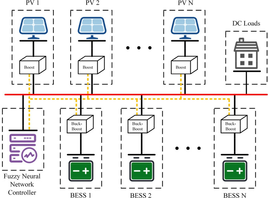
Fig.1.Schematic of the IDCMG archite cture.
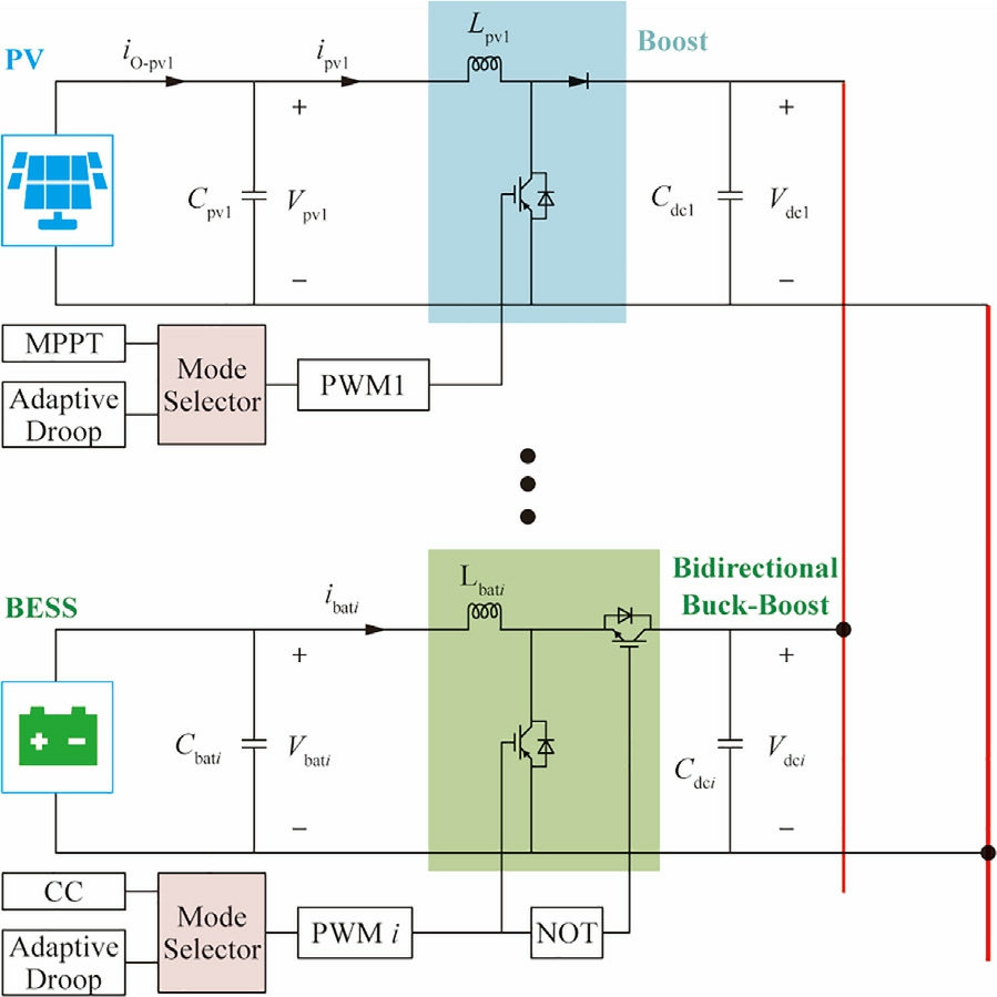
Fig.2.System architecture of PV-storage IDCMG.
Therefore, based on Kirchhoff’s laws, the system statespace equations can be formulated as follows:

where Vpvi, Vbati, ipvi, and ibati denote the port-side voltage and current of the PV and energy storage systems, respectively.D pvi and Dbati denote the control duty cycles of the PV and the energy storage.
1.2 Configuration of the two-layer FNNC
The proposed system employs a coordinated strategy using the two-layer FNNC to achieve the overall control objectives.The first-layer FNNC makes high-level decisions on microgrid operating modes, whereas the secondlayer FNNC adjusts the power distribution among the multi-DG system based on the results of the first-layer FNNC.The two FNNC layers collectively form a tree structure, which significantly simplifies the computational complexity while maintaining the number of inputs.Additionally, we employed ANFIS to realize the FNNC,as ANFIS is clear and straightforward to implement.Fig.3 depicts the two-layer FNNC control architecture.
The inputs to the first-layer FNNC include the bus voltage deviation, ΔVdc, and the SOCT of the energy storage,wherein the SOC was reconstructed using weighted factors.The operating mode command, Z, was generated after the FNNC output, Z0, was processed through multi-step hysteresis comparison.Furthermore, Zis decomposed into the PV operating command, n, and the energy storage operating command, m, which represent the reference number of the PV operating in the MPPT mode and the reference number of the BESS operating in the CC charging mode within the IDCMG,respectively.The second-layer FNNC further incorporates the powervoltage slope of each PV unit and the SOC of each energy storage unit based on the output of the first layer to derive the droop modification parameters, kpv_i and kbat_i, for each PV and energy storage.This enables greater precision in the power regulation for each DG unit.
1.3 Detailed design of ANFIS
The two-layer ANFIS model structure used in this study includes a dual-input, single-output system based on the Takagi-Sugeno (T-S) fuzzy model.This helps in effectively combining the descriptive ability of fuzzy logi c with the learning capability of neural networks.We established a preliminary fuzzy rule set based on the existing control experience in this field.Consequently, we useda hybrid backpropagation-least squares estimation (BPLSE) learning algorithm to dynamically optimize the adjustment of the antecedent and consequent parameters in the fuzzy control model.Fig.4 depicts the typical fivelayer structure of the ANFIS.
In this ANFIS, the multi-layer structural design endows the system with powerful modeling and reasoning capabilities.For a network with n inputs and m rules, thexn inputs are assigned first.The first layer is the fuzzification layer.We quantified the membership of each input data point to the fuzzy set using the Gaussian membership function with the smooth and continuous characteristics ofthe dynamic response as the activation function.This can be expressed as follows:
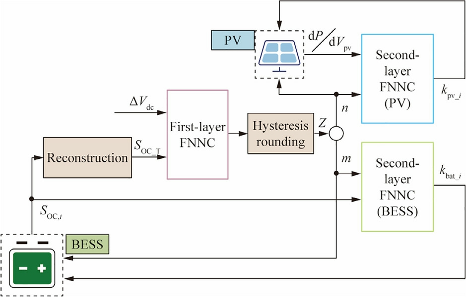
Fig.3.Schematic of the two-layer FNNC archit ecture.
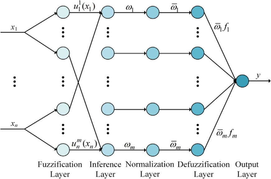
Fig.4.Schematic of the ANFIS structure.
where denotes the membership degree of the j-th node in the i-th input group and
  and
and  denote the shape parameters of the Gaussian membership function.The second layer is the inference layer; it helps in quantifying the degree of matching for each control rule and assigning the corresponding weight, ω, to each possible output result, as follows:
The third layer is the normalization layer; it helps in normalizing the weights, which ensures that the influence ofeach rule in the fuzzy inference process remains within aconsistent scale.
The defuzzification layer is the fourth layer; it helps in converting the fuzzy inference results into explicit output values.The output of each rule is represented by a linear equation, given as follows:
In (8), the fuzzy parameter,  , represents the Takagi-Sugeno linear equation parameter determined using the least squares estimation algorithm.This method minimizes the sum of the squared errors between the fuzzy rule outputs and the target outputs.This ensures that the model can efficiently fit the relationship between the inputs and outputs.
The fifth layer is the output layer; it helps in calculating the fuzzy output using the weighted sum method and in achieving global nonlinear mapping from input to output.

The selection of the operating modes and coordinated power distribution in multi-DG IDCMG can be effectively achieved by adopting this ANFIS architecture.
2 Operating mode design based on the first-layer FNNC
The first-layer FNNC determines the operating mode reference signal, Z, of the system based on the inputs, ΔVdc and SOCT.It reflects the degree of deviation from the bus voltage reference value for ΔVdc and is defined as follows:
To ensure that the overall SOC of the system accurately represents the SOC of each energy storage unit in realtime, we designed a strategy to reconstruct the SOC weight ofthe energy storage system.The specific details are presented in Subsection 2.1.
2.1 Adaptive SOC weight reconstruction strategy
We designed the adaptive SOC weight reconstruction strategy based on the proximity of the SOC of each energy storage unit to the charging and discharging boundaries,thereby forming the reconstructed SOCT through weighted averaging.It is calculated as follows:
where SOCi denotes the SOC of the i-th energy storage unit and ωi denotes the weight of the SOC for the i-th energy storage unit.This ensures that SOCT reflects the proximity of SOCi to its upper (SOCH) or lower (SOCL)limit s as accurately as possible.The strategy is designed such that the closer the SOC of an energy storage unit is tothe critical value, the greater its influence on SOCT[24]; hence, it is assigned a higher ωi value.The sigmoid function exhibits the steepest slope near x = 0, and the slope gradually approaches 0 as it nears the critical region.Therefore, it ensures that the weight functi on increases rapidly when SOCi approaches the lower or upper limit.According to the SOC design requirements in this study,the sigmoid function is defined as follows:
where α, β, η, and φ denote the sigmoid shape parameters.Inparticular, α determines the steepness of the curve, β determines the horizontal shift, η determines the output amplitude of the curve, and φ determines the vertical offset ofthe curve.The weight coefficient increases based on the sigmoid function as the SOC approaches the upper or lower limits.It remains at 1 when the SOC is non-critical and is set to 0 when the energy storage unit is not connected or is out of service due to failure.To achieve this design effect, β is set to 0 and φ is set to 1.The final weight is calculated as follows:

where α and η control the degree of weight amplificationas the SOC approaches the threshold, whereas ε defines the range within which the SOC is considered to be close to the threshold.This method dynamically adjusts the weight based on the relative position of the SOC to the threshold,assigning higher weights as the SOC approaches the upper or lower thresholds.This dynamic adjustment mechanism accurately reflects the actual state of the battery and its impact on the overall SOC.By adjusting the parameters α, η, and ε, the designed first-layer FNNC exhibits good adaptability to various types and specificationsof batteries.
2.2 Specific decomposition strategy of the operating mode signal Z
Based on the FNNC output, Z, it is decomposed into specific operating commands for the PV and energy storage systems, thereby selecting the most suitable operating mode for each DG unit.Fig.5 depicts the relationship between the decomposition of Z into n and m.
It can be observed that when the mode-switching signal,Z, is low, the BESS switches between the CC charging and adaptive droop modes, with all the PV modu les operating in the MPPT mode.This compensates for the bus voltage drop and increases the SOC of the BESS.When the modeswitching signal, Z, is high, the PV modules switch between the MPPT and adaptive droop modes, whereas the BESS operates only in the CC charging mode.This alleviates the increase in the bus voltage and reduces the SOC of the BESS to prevent overcharging and is given as:
The mode selector for the PV and BESS is designed based on the rules presented above, and this strategy also presents good scalability for IDCMG with various DG configurations.
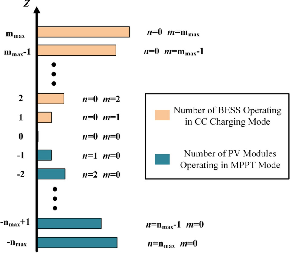
Fig.5.Schematic of the decomposition of mode signal Z into n andm.
2.3 Design of membership functions and fuzzy rules
The input values of the fuzzy neural network were fuzzified based on the ANFIS structure depicted in Fig.4.We used seven fuzzy subsets to balance the control accuracy and speed, including Gaussian membership functions that are smoothly continuous in their derivatives.For the proposed system, the voltage deviation is constrained within±5% of the rated value to ensure the optimal performance of the IDCMG.Therefore, the fuzzy set universe of discourse for ΔVdc is set to [0.05*Vref, 0.05*Vref], with the linguistic variables {NB, NM, NS, Z, PS, PM, PB}.The fuzzy set universe of discourse for SOCT is set to [0,100], with the linguistic variables {VS, S, MS, M, MB,B, VB}.The initial control rules of the first-layer FNNC are based on the following principles:
When ΔVdc is large and SOC is high, it indicates an overall energy surplus in the system.In this scenario, the mode-switching command, Z, must be increased to reduce the DG output and utilize the excess energy.Conversely,when ΔVdc is small and SOC is low,it indicates an overall energy deficit in the system.In this scenario, the modeswitching command, Z, must be decreased to increase the DG output and store the excess energy.
The entire control system achieves self-learning through the ANFIS structure.It adjusts its membership functio n parameters,  and
and  , using the BP algorithm and adjust s its consequ ent linear equation parameters, pj, using the LSE algorithm, thereby optimizing the ANFIS control performance.
2.4 Filtering of FNNC output signals
The continuous value, Z0_ini, output by the fuzzy neural network must be converted into a stable integer signal, Z0,owing to the specific characteristics of the mode signal and the need to ensure system operation stability.Therefore,a multi-step hysteresis comparator is included after the firstlayer FNNC, as shown in Fig.6.
After obtaining the integer value, Z0, using the hysteresis comparator, we implemented a mode-maintaining module to ensure a minimum operating time (reaching the minimum duration threshold tmin) for the system in the selected mode.No new switching commands are accepted before this threshold is satisfied, as shown in Fig.7.
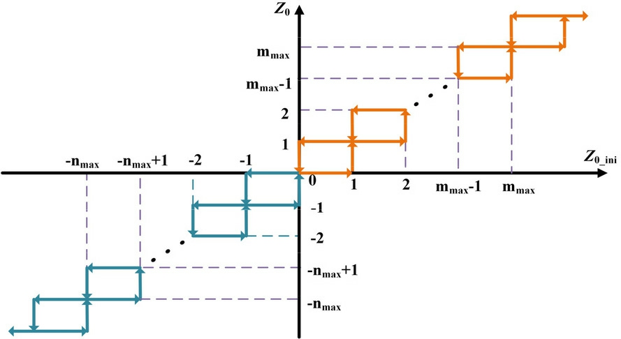
Fig.6.Schematic of the multi-stage hysteresis comparator.
This configuration is designed to prevent large voltage fluctuations from causing the FNNC output, Z, to undergo multi-step oscillating transitions, which could cause unnecessary frequent switching of the operating modes.The introduction of a dual filtering mechanism reduces the impact of the transient responses during mode switching.
2.5 Logic of the mode-switching sequence
The system monitors the changes in command signals, n and m, in real-time, which are denoted as Δn and Δm,respectively.Based on these changes, the system determines the adjustment sequence strategy for the operating modes of each DG unit.The values of Δn and Δm are calculated as follows:
where n(t) and m(t) denote the current mode signals and n(t-1)and m(t-1) denote the previous mode signals.The modeswitching process is designed as shown in Fig.8 to prevent the overcharging or over-discharging of the energy storage and to enhance the ability of the system to respond to PV mode transitions.
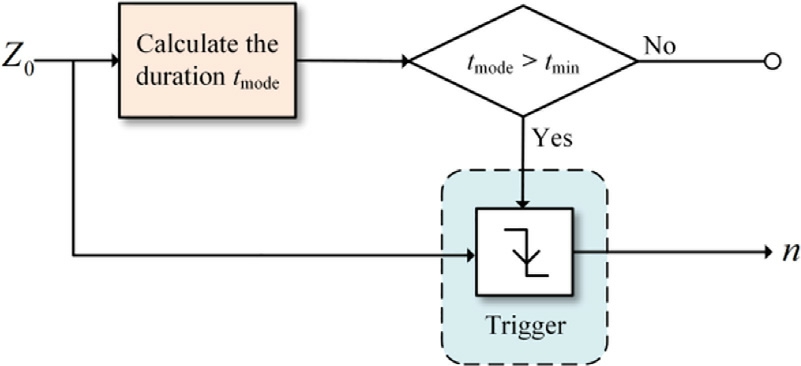
Fig.7.Schematic of mode maintaining module.
Thus, as n increases, the PV unit with the highest power-voltage slope |dP/dV| first enters the MPPT mode.Conversely, as n de creases, the PV unit with the highest maximum power point(MPP)power first enters the droop mode.This ensures that mode switching provides sufficient regulation capacity to the system.As m increases, the BESS with the lowest SOC first enters constant-current charging mode.Conversely, as m decreases, the BESS with the highest SOC first enters the droop mode, thereby preventing the overcharging or over-discharging of the energy storage units.
The FNNC control strategy enables each DG in a multi-DG IDCMG to adaptively determine the appropriate operating mode.This helps in overcoming the problem ofmode mis-switching that can occur when using the existing DBS control strategies due to insufficient control precision and large bus voltage fluctuations in multi-DG systems.
3 Power allocation strategy based on the second-layer FNNC
After the first-layer FNNC defines the operating mode,each DG operating in the droop mode must adaptively adjust its output power to match its specific characteristics.Tothis end, we designed adaptive droop modification parameters for each DG group based on the secondlayer FNNC.Consequently,we designed separate FNNCs for PV and energy storage, each with power-proportional adjustment characteristics, owing to the different characteristics of PV and energy storage.Fig.9(a) and 9(b) depict the schematic P-V characteristic curves of the PV and BESS in the designed IDCMG, respectively.
where kpv_ini and kbat_ini denote the initial droop coeffi-cients and kpv_max, kpv_min, kbat_max, and kbat_min denote the maximum and minimum droop modification parameters for the PV and BESS.Pmpp denotes the PV MPP power, Pch_max and Pdisch_max denote the maximum charging and discharging powers of the batte ry,and Vref_min and Vref_max denote the lower and upper bus voltage limits,which are 0.95*Vref and 1.05*Vref,respectively.The droop characteristics of each DG group can be expressed as follows:

where Ppv,i and Pbat,i denote the output power of the PV and BESS, respectively (consi dered to be positive when flowing into the DC bus).
3.1 PV FNNC with power-proportional modification characteristics
In the PV FNNC, the selected input variables include the reference value, n, for the number of PV modules operating in the MPPT mode, with a fuzzy set universe of discourse of [1, nmax + 1], and the absolute value of the power-voltage slope |dP/dV| at the PV port, with a fuzzy set universe of discourse set to [0.7*|dP/dV| max, |dP/dV|max].Both the inputs are fuzzified using the same sevenlevel linguistic varia ble set: {VS, S, MS, M, MB, B, VB}.
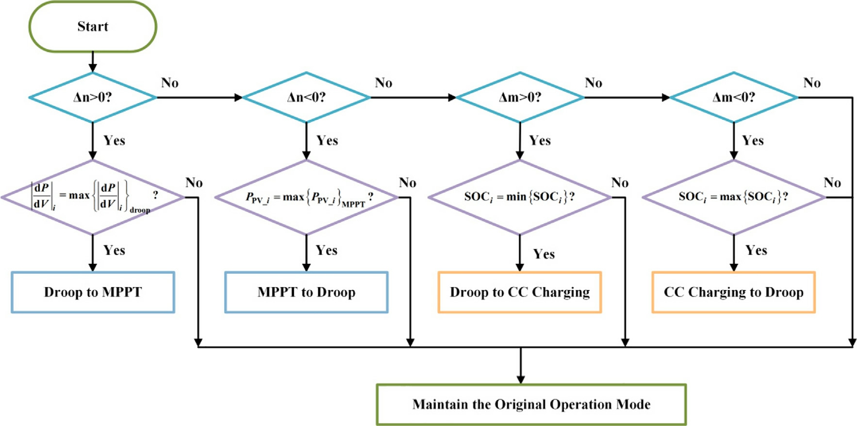
Fig.8.Schematic of the mode-switching logic.
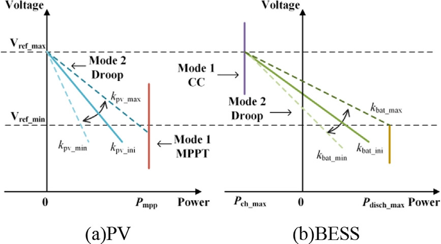
Fig.9.Power-voltage characteristic curve.
After incorporating the droop modification parameter,the PV equation is transformed as follows:
where λpv,i denotes the droop modification parameter for the PV system.However, directly applying λpv,i in a multiplicative form can cause the uneven distribution of gain among the regulation capabilities of the DG units.To ensure that the output of the PV FNNC can achieve power-proportional modification based on the PV output power, Ppv,i, λpv,i is redefined according to a specific rule,as follows:
where kpv,i denotes the transformed PV droop modification parameter, which serves as the output variableof the second-layer PV FNNC.This ensures that kpv,i linearly correlates with the output power, Ppv,i, based on a linear function, with the same rate of change.Subs tituting t he transformed expression (19) into the original (18) yields:
By controlling the output variable, kpv,i, of the secondlayer FNNC, the system can adaptively adjust the output power, Ppv,i, of each PV group according to (20).To provide Ppv,i with an adjustment capability of ± 50%, the universe of discourse for kpv,i is set to [0.5, 1.5].The value ofn reflects the number of PV units with voltage regulation capability, and |dP/dV| represents the strength of the regulation capability of each PV unit.Consequently, the initial fuzzy rule design is based on the following principles:
When n is large and |dP/dV| is high, kpv,i is increased to enhance the output of the PV units operating in the droop mode, thereby compensating for the bus voltage drops.Conversely, when n is small and |dP/dV| is low, kpv,iis decreased to reduce the output of the PV units in the droop mode, thereby preventing the risk of the PV power exceeding the limits.
The FNNC can dynamically adjust the output power levels of each PV unit in real time using this control strategy, thereby effectively ensuring the operational efficiency of the entire PV system.
3.2 BESS FNNC with power-proportional modification characteristics
In the management of the BESS, the output power must be accurately controlled based on the SOC differences among the BESS units to achieve a balanced SOC across all the units.The droop expression for the BESS after introducing the droop modification parameters is given as follows:
The selected input variables include two parameters: the reference value, m, which represents the number of energy storage units in the CC charging mode, with a universe of discourse set to [1, mmax + 1], and the current SOCi of each energy storage unit, with a universe of discourse set to[0, 100].The linguistic variables for both the inputs include {VS, S,MS,M,MB,B, VB}.For the output control, we applied the transformation method proposed in Section 4.1.Furthermore, the adaptive VD equation for the energy storage, derived using ANFIS based on (19)and (21), is given as follows:
At this point, the energy storage power also exhibits a power-proportional change characteristic with kbat,i.The initial fuzzy rules in the BESS FNNC are formulated as follows.When the value of m is high and SOCi is low, kbat,i isdecreased, which simultaneously decreases the discharge power of the energy storage units, thereby slowing down the rate of voltage increase and effectively avoiding the risk ofexcessive discharge.Conversely, when the value of m is low and SOCi is high, kbat,i is increased, which causes the energy storage units to increase their discharge, thereby compensating for the bus voltage drop and preventing the overcharging of the energy storage units.
In summary, the second-layer FNNC enables proportional and accurate control of the output obtained from the PV and BESS.This effectively ensures the stability of the IDCMG bus voltage and the safe operation of the BESS units.This approach enhances the overall system performance and reliability while optimizing the efficient utilization of DG within the IDCMG.
4 Experimental verification
We constructed a typical multi-DG IDCMG model comprising six PV systems and BESSs, respectively.We used an HIL experimental platform, comprising the OPAL-RT OP5700 real-time digital simulator and the NI PXIe-1071 modular control platform, to model various components of the DC microgrid.This helps demonstrate the effectiveness of the proposed two-layer FNNC control strategy under various operating conditions.Table 1 presents the details of the experimental setup.
The main circuit of the multi-DG system was equivalently simulated by the OP5700, whereas the control partwas implemented using these two devices as virtual controllers, thereby enabling the hardware execution of control algorithms.The devices were connected to the host computer using the Modbus/TCP protocol, and the test re sults were displayed in real time on the Tektronix MOS3024 oscilloscope.Fig.10 depicts the experimental se tup.
Table 1 Simulation parameter configuration.

EqEqHo OPMRT PXSeLa uipmentuivalent Componentst Software 5700ain circuit, primary control-LAB Ie-1071condary controlbVIEW
Table 2 presents the specific configuration details of the microgrid simulation parameters.
Different initial battery SOCs are used in the BESS unit tosimulate various operating conditions.Additionally, we designed six operating conditions for the PV array groups todetermine the complex ity of PV power generation under the climate influences.The DG specifications are standardized for analysis, as shown in Table 3.
The first layer of the control strategy focuses on the mode selection and requires the coverage of more extreme scenarios and greater diversity.Conversely, the secondlayer FNNC emphasizes the system power allocation,necessitating fine-tuning based on the actual operational data.Therefore, we established the initial fuzzy rules for the first-layer FNNC based on expert knowledge, which forms the foundation of the ANFIS control system.The proposed model is initially trained using 50 sets of the simulation result data.The fuzzy rules and output parameters are gradually adjusted through iterative training to enable the first-layer FNNC to accurately generate the operating mode command, Z, of the system.For the second-layer FNNC, real-world data obtained from the energy selfsufficiency system in the Karamayli service area in Xinjiang are used as the background.A total of 2,000 microgrid operation data sets, corresponding to the first-layer mode quantity commands and optimized by BP-LSE, are collected as the samples to ensure comprehensive model learning and validation.
4.1 Validation of the first-layer FNNC performance
Fig.11 depicts the time-varying step load employed in this study.
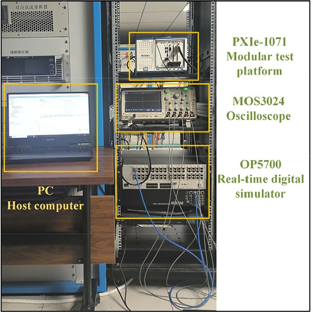
Fig.10.HIL experimental platf orm.
Table 2 Simulation parameter configuration.
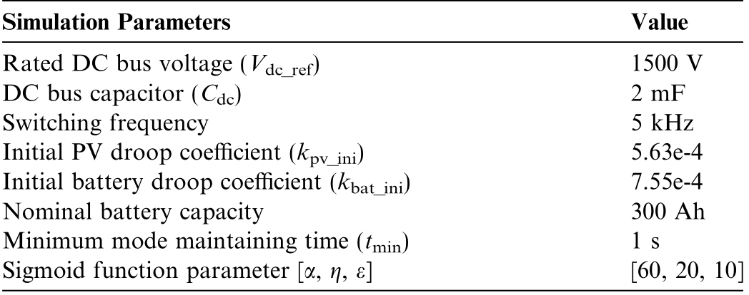
Simulation ParametersValue Rated DC bus voltage (Vdc_ref)1500 V DC bus capacitor ( Cdc Switching frequency5 kHz Initial PV droop coefficient (kpv_ini)5.63e-4 Initial battery droop coefficient (kbat_i7.55e-4 Nominal battery capacity300 Ah Minimum mode maintaining time (tm Sigmoid function parameter [α, η, ε][60, 20,10])2 mF ni)in)1 s
Table 3 DG configuration.

PV NumExternal EnvironmBESS NumS PV 11000 W/m2 ,25 ℃BESS 120 PV 2900 W/m2 ,25 ℃BESS 225 PV 3800 W/m2 ,25 ℃BESS 330 PV 4700 W/m2 ,25 ℃BESS 435 PV 51000 W/m2 ,35 ℃BESS 540 PV 61000 W/m2 ,45 ℃BESS 645 berentberOCi
It can be observed that the load power increases at 2s,4 s, and 6 s, then gradually decreases at 8 s, 10 s, 12 s, and 14 s, and finally increases again at 16 s and 18 s, with each power change accounting for 200 kW.The changes in the power cause variations in the first-layer FNNC inputs,ΔVdc and SOCT, which subsequently cause changes in the FNNC output, Z0.Fig.12 depicts the input of the first-layer FNNC.
Fig.13(a) depicts the process of obtaining the modeswitching command, Z, after Z0 passes through the mode holding module.Subsequently, Z is decomposed inton and m based on (7), as shown in Fig.13(b).
Subsequently, the current operating modes of the PV and energy storage systems are selected according to the predefi ned plan based on the n and m commands issued by the central FNNC.Figs.14 and 15 depict the power curves of the PV and energy storage.At 3.4 s, m increases to 1, indicating that one energy storage unit operating in the droop mode switches to the CC charging mode.At 5.4 s, m decreases to 0, indicating that the numberof energy storage units operating in the current-source mode is reduced to 0,and the energy storage exits the CC charging mode.Similarly, at 7.46 s, two PV units operating in the droop mode switch to the MPPT mode to counteract the increase in the load power.Thus, the mode switching ofall the DGs is based on the current FNNC control command, Z.

Fig.11.Variation of load power.
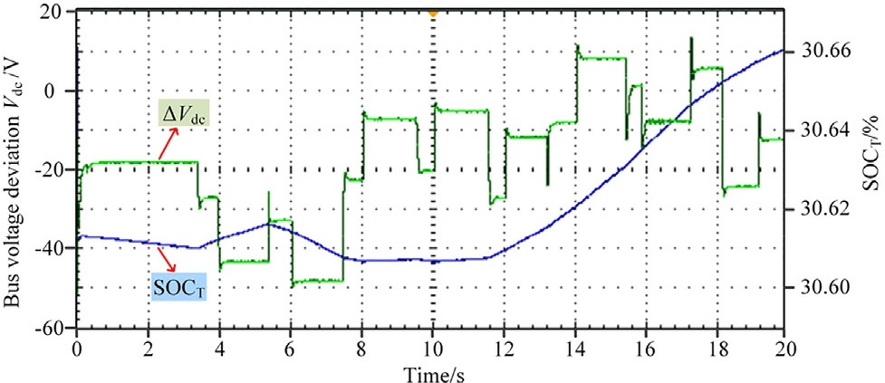
Fig.12.First-layer FNNC inputs.
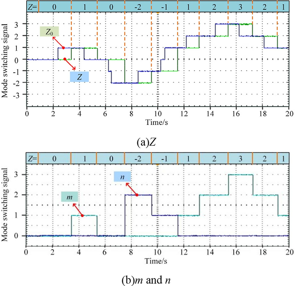
Fig.13.Operating mode signals.
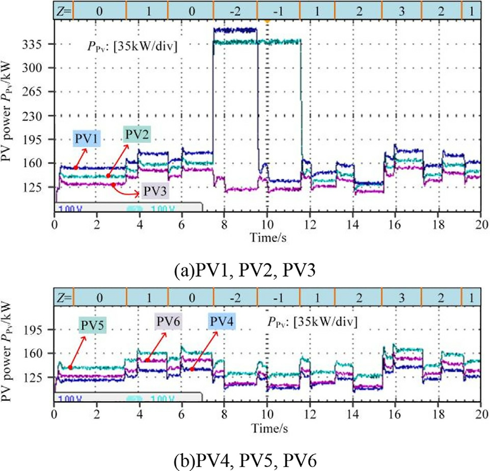
Fig.14.PV output power.
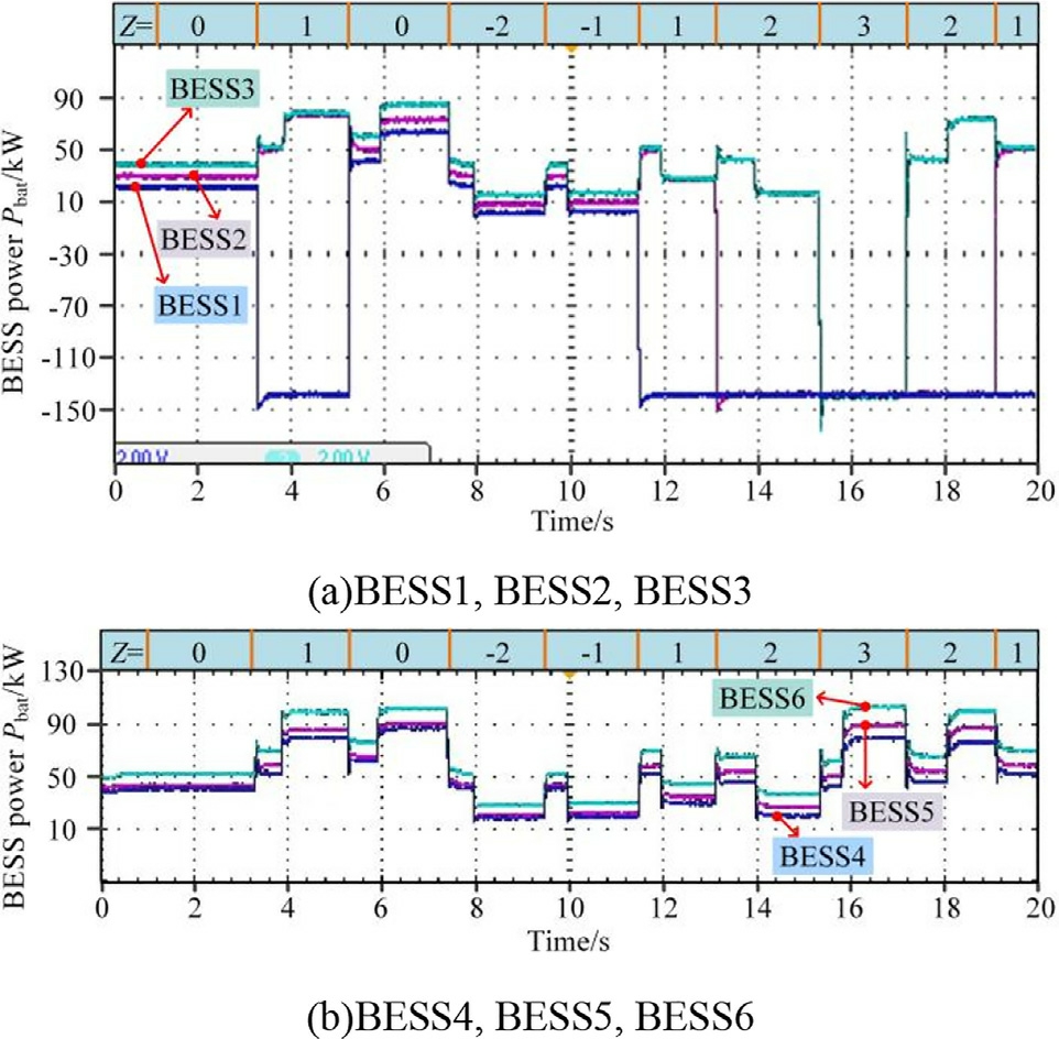
Fig.15.BESS power.
The PV power curve depicted in Fig.14 shows that at 7.46 s, n abruptly increases to 2, triggering a switch of the two PV units with the highest |dP/dV| from the droop mode to the MPPT mode, as shown in Fig.8.As n decreases, the PV unit with the highest current, Pmpp, is selected to switch back to the droop mode.This prevents the frequent mode switching of units with low output due to minor fluctuations.Based on the BESS power curve depicted in Fig.15, BESS units 1 through 4 enter the CC charging mode sequentially after 10 s, based on their SOC values from low to high.Subsequently, they exit the CC charging mode in the reverse order, from high to low SOC.This approach ensures that the BESS units with low SOC receive more charging opportunities, whereas those with higher SOC complete charging first.
4.2 Validation of the second-layer FNNC performance
The second-layer FNNC uses the load conditions described in Subsection 5.1 to verify the power regulation capabilities of each DG.Fig.16 depicts the |dP/dV| for each PV unit, which serves as the input for the secondlayer PV FNNC.
When operating in the droop control mode, differences inthe external environment of each PV unit present different P-V characteristic curves, causing variation in the |dP/dV| values.It can be observed that PV1, with a steeper characteristic curve, exhibits a larger |dP/dV|.At 7.46 s,when PV1 and PV2 switch to the MPPT mode, their |dP/dV| values rapidly drop to near 0.At 9.77 s, Z = 1,which causes PV1 to re-enter the VD operating mode,which causes a rapid increase in |dP/dV|.Fig.17 presents the output results, kpv_i and kbat_i, of the second-layer FNNC.
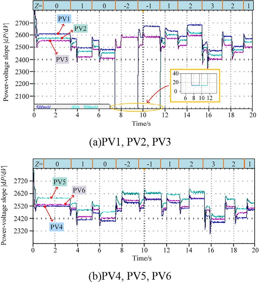
Fig.16.Slope of the P-V characteristic curve |dP/dV|.
The proposed system exhibits the same output power while operating in the VD mode if the second-layer FNNC isnot employed due to the identical models of each group ofDGs, which is not conducive to optimal operational conditions.By implementing the second-layer FNNC,the system can ad aptively adjust the droop output power ofeach group of DGs based on the current operational conditions, external PV environment, and energy storage SOC.This is achieved using kpv and kbat, as defined in(21) and (22).This adjustment helps in preventing the PVoverlimits and energy storage overcharging and overdischarging.
Additionally, we performed comparative tests between enabling and disabling the second-layer FNNC to verify the effectiveness of the proposed control strategy.Fig.18(-a)-(f) depict the SOC conditions of each group of energy storage before and after enabling the second-layer FNNC,whereas Fig.18(g) depicts the SOCT after reconstructing the weights.
For BESS units with different SOCs, BESS1 and BESS2, being close to the charging/discharging boundary,present a greater impact on SOCT.Consequently, SOCT follows a similar pattern to BESS1 and BESS2.After the power modification by the second-layer FNNC, BESS1 toBESS4, which have lower SOCs, stored more energy when compared with the case when no modification was applied, whereas BESS5 and BESS6 accounted for a greater portion of the load power.Therefore, this method effectively prevents the individual BESS units from overcharging or over-discharging and promotes the convergence of all the SOCs.It also ensures that BESS units near the charging/discharging boundary ha ve higher weights when used as the fuzzy neural network inputs,enabling SOCT to more effectively influence Z of the first-layer FNNC.
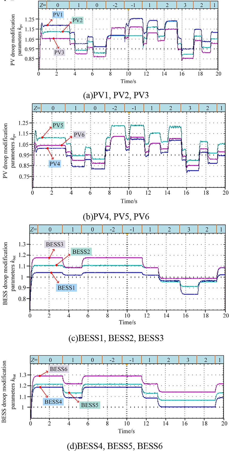
Fig.17.Droop modification parameter.
Fig.19 depicts the DC bus voltage curves before and after enabling the second-layer FNNC.An analysisof the two curves provided their respective mean values,standard deviations (STD), and peak-to-valley (PTV) values.Table 4 presents the specific results.
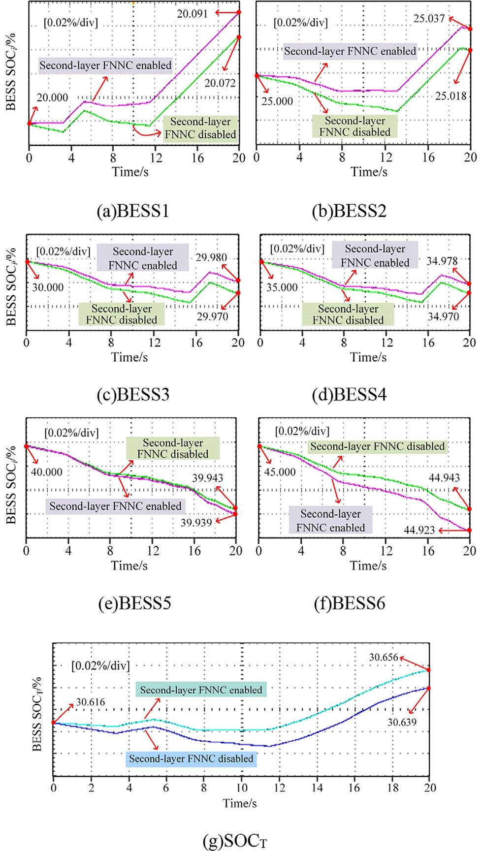
Fig.18.BESS SOC.
The data presented in Table 3 show that after introducing the second-layer FNNC, excessive fluctuations in the bus voltage were successfully suppressed, as indicated by the significant reduction in the STD and PTV values.This indicates an improvement in the bus voltage stabi lity,thereby demonstrating the effectiveness of the secondlayer FNNC in coordinating power distribution among the DGs within the IDCMG.
In summary, by using the second-layer FNNC, the adaptive modification of DG allows for effective powerproportional adjustment and allocation of DG output,preventing individual DGs from being overloadedor underutilized,thereby enhancing the operational efficiency and energy utilization of the IDCMG.
4.3 Effectiveness of the control strategy under time delay conditions
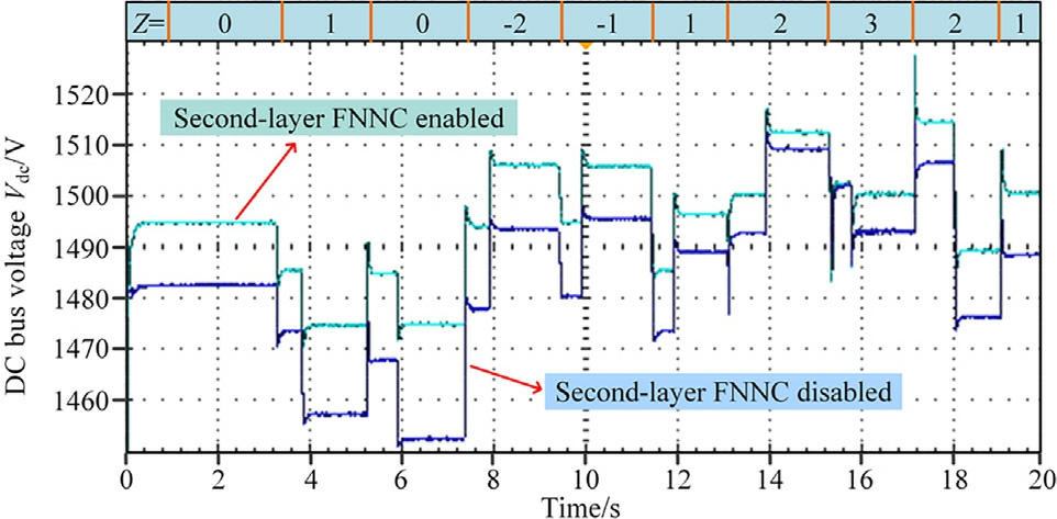
Fig.19.DC bus voltage.
Table 4 DCbus voltage analysis results.

Indsecsec M 1414 ST PT exond-layer FNNC disabledond-layer FNNC enabled ean (V)82.1393.61 D 16.0511.75 V (V)63.6756.81
The FNNC exhibits inherent robustness and effectively mitigates the impact of signal delays.Furthermore, hysteresis control enhances the ability of the system to reject the disturbances caused by input fluctuations through the implementation of nonlinear thresholds.Additionally,the mode-maintaining module suppresses short-term mode switching by employing a time-locking strategy.The combination of these features ensures that the FNNC maintains reliable control performance even under significant delay conditions.To validate the effectiveness of the proposed control strategy in the presence of time delays, we introduced bidirectional delays between the measurement module and the FNNC controller, as well as between the FNNC controller and the primary controller.Delay values of20 ms, 50 ms, 100 ms, and 150 ms were tested to cover both the typical and extreme operational scenarios.Figs.20 and 21 present the experimental results.
The blue line in the figure represents the control group without delay, and the green line repres ents the experimental results after applying a delay.In Fig.20(a), an appropriate DC bias is applied to the oscilloscope channel to enhance visibility due to the small voltage difference.Table 5 presents the bus voltage and SOCT deviations,which were analyzed based on the results.
It can be observed that the response is nearly identical tothat of the no-delay control group at a delay of 20ms.The STD of the bus voltage increases by only 0.84, whereas the ΔSOCT increases by 0.0012 at a delay of50 ms.At larger delays, such as 100 and 150 ms, the bus voltage fluctuations are intensified.However, none ofthese fluctuations affect the stabilized operation for a brief period.The robustness of the FNNC control strategy tobrief time delays on the millisecond scale is further substantiated.
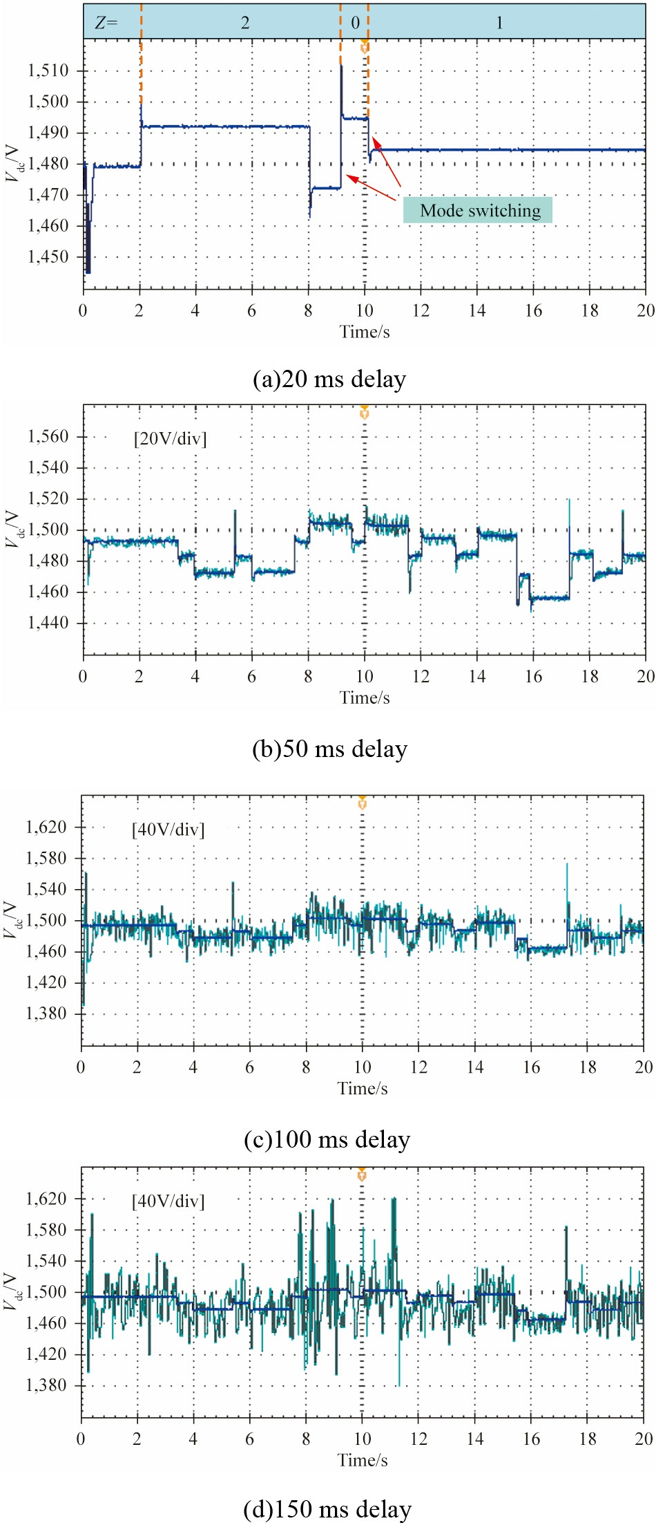
Fig.20.DC bus voltage under the effect of delay.
4.4 Comparison of the proposed control strategy with other methods
To demonstrate the performance and innovation of the proposed control strategy, we conducted comparative experiments to evaluate the ability of three control strategies under various operating conditions.
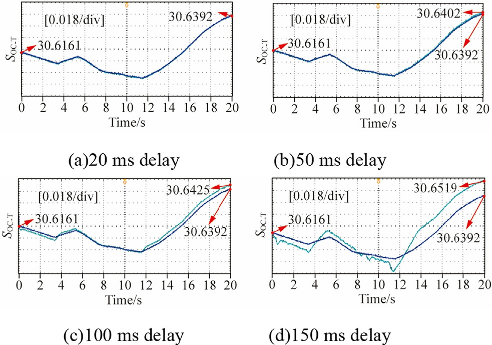
Fig.21.SOCT under the effect of delay.
Table 5 Analysis results of bus voltage and SOCT under different delay effects.

Delay (Mean (STPTV (ΔSO 0 1,485.513.84.550.053 201,485.513.100.850.053 501,485.314.151.050.054 1001,483.822.225.410.057 1501,482.932.244.710.093 ms)V)DV)CT 9 41135 6 50216 6 25517 7 23592 3 66464
Strategy1: The voltage control strategy based on the system source load state, which is used in [16].
Strategy2: The fuzzy logic control (FLC)-based coordinated control strategy, which is used in [17].
Strategy3: The two-layer FNNC coordinated control strategy proposed in this study.
To enhance the comparability of the three control strategies, the following constraints were applied in the comparative experiments:
(1) The same initial droop coeffici ents were adopted.
(2) The SOCT of the energy storage systems was calculated based on the proposed reconstruction strategy.
(3) The system configuration was normalized to a structure of six PV units and BESS units, respectively,with the rated voltage normalized to 1500 V.
1) Validation of operation mode selection strategy
The variations of the BESS SOCT and DC bus voltage represent the effectiveness of various mode selection strategies.Therefore, we primarily analyzed these two parameters in this study.The mode selection modules of the three control strategies are activated at 2 s.Subsequently,the load power is abruptly increased from 500 kW to 800 kW at 8 s to evaluate the mode-switching capabilities of the various control strategies.The experimental results are presented as follows:
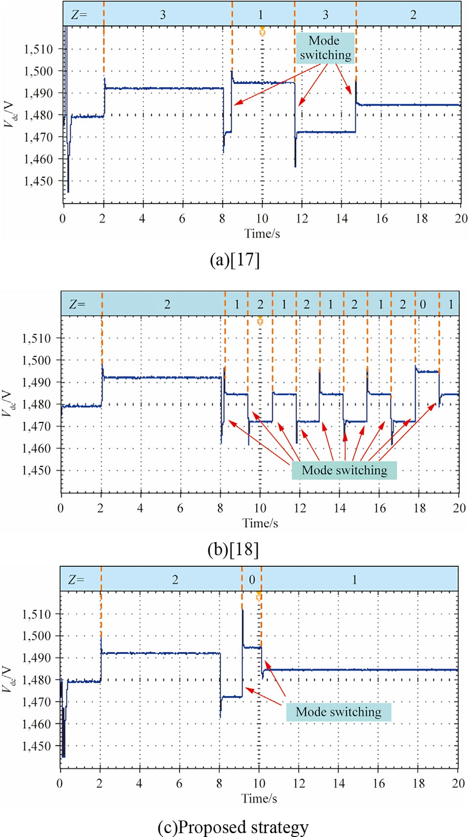
Fig.22.DC bus voltage under various control strategies.
Table 6 Analysis results of mode switching.

MethodMode selection judgment tiVoltage SMean (SOC[16]2 or 313.99331,484.830.68[17]214.01911,482.830.69 Proposed strate16.49111,485.530.69 mesTDV)1 92 9 21 gy083
Table 7 SOC results of each BESS group.

M BEBEBEBEBEBE[16202529343944[17202530354045 Pr202529343944 ethodSS1SS2SS3SS4SS5SS6].0342.0109.9899.9893.9647.9649].0216.0047.0042.0045.0041.0044 oposed strategy.1774.1782.9748.9749.9493.9501
Table 8 Analysis results of SOC balancing degree.

M SOSOSO[16329.324[17329.324 Pr329.224 ethodC meanC STDC range].4925282.9307].5073494.9824 oposed strategy.5342570.7727
Table 6 presents the analysis results of the modeswitching effect for each strategy.In [16], a large-scale abrupt mode switching was observed due to a significant and sudden change in the load power, as dictated by the power criterion of this strategy.This caused a sharp increase in the bus voltage STD,although it eventually stabilized and returned to normal, as shown in Fig.22(a).In[17], the operating mode of the system is set based on FLC;however, the lack of the two-layer filtering mechanism proposed in this paper leads to a cyclic switching of the operating mode, causing periodic fluctuations in the bus voltage, as shown in Fig.22(b).The proposed strategy is calculated based on the first-layer FNNC.Subsequently,the system immediately determines the appropriate operation mode after the multi-stage hysteresis controller and the mode-maintaining module, thereby avoiding the frequent mode switching and the occurrence of misswitching.
2) Validation of adaptive power alloc ation performance
In this section, we compare the power allocation capabilities of various control strategies by operating [16,17],and the proposed strategy under the same operating mode.All three strategies operate in the mode where all the PVs operate in the MPPT mode, two groups of energy storage operate in the CC charging mode, and four groups of energy storage ope rate in the droop control mode.The load power is set to 500 kW (which does not trigger mode switching).The initial SOCs of the six BESS groups are set to[20,25,30,35,40,45],respectively.Table 7 presents the SOC balance of the system after 20 s of operation.
It can be observed that the introduction of the SOC weight reconstruction strategy in the proposed method dynamically increases the weight of the BESS unit when itsSOC approaches the boundary.This drives the second-layer FNNC to allocate higher charging or discharging power to the unit, thereby reducing the SOC gap between the unit and other units.Table 8 presents the degree of SOC balancing among the BESS groups based on the analysis of the above data.
The proposed method demonstrates superior performance in terms of the SOC balancing,as shown in Table 8.Both the SOC STD and the SOC range are lower than those of the strategies presented in refs.[16,17].The proposed control strategy effectively mitigates the risks of overcharging or over-discharging under extreme SOC conditions while simultaneously promoting energy balancing among the energy storage units.
5 Conclusion
In this study, we propose an adaptive coordinated operation control strategy based on the two-layer FNNC for the IDCMG integ rating multiple distributed PV and BESS units.This strategy exhibits the following features:
1) The first-layer FNNC intelligently defines the operating mode of the system.When compared with the conventional DBS methods, it considers both the DC bus voltage and BESS SOC.The output of the FNNC is refined through a multi-step hysteresis comparator and the mode-maintaining module,thereby ensuring that each DG in the system operates in the mode best suited to the current conditions.
2) An overall mode-switching process was designed using the PV power-voltage slope and the SOC of each BESS unit to optimally determine the units that must be priori tized for mode switching.This ensures that the system exhibits sufficient regulation capabilityand prevents the overcharging or overdischarging of the BESS units.
3) Based on the optimal operating modes determined bythe first-layer FNNC, the second-layer FNNC adjusts the droop modification parameter of each DG in real-time corresponding to their specific characteristics an d makes power-proportional adjustments to the DG output.This effectively prevents the PV power from exceeding the limits and balances the SOC of the BESS.
In future works, two aspects must be further analyzed:(1) An adaptive control strategy must be developed for the energy storage boundary.This strategy can help in preventing the energy storage power from exceeding its limits under extreme conditions.(2) Based on the large-scale integration of PV, establishing a more accurate nonlinear mapping model between PV |dP/dV| and the PV MPP power could further reduce the sensitivity of the secondlayer FNNC to its inputs.
CRediT authorship contribution statement
Hao Pan: Software, Data curation, Methodology, Writing - original draft.Limin Jia:Conceptualization,Writing- review & editing.
Declaration of competing interest
The authors declare the following financial interests/personal relationships which may be considered as potential competing interests: Hao Pan is currently employed by State Grid Ningxia Electric Power Yinchuan Power Supply Company.
Acknowledgments
This work was supported by National Key R&D Program of China under Grant, (2021YFB2601403).
References
-
[1]
N.Poursafar, M.J.Hossain, S.Taghizadeh, Distributed DC-bus signaling control of photovoltaic systems in islanded DC microgrid, CSEE J.Power Energy Syst 8 (6) (2022) 1741-1750. [百度学术]
-
[2]
S.Zheng, Z.Wu, L.J.Song, et al., Distributed economic control strategy based on reinforcement pinning control for microgrids,Electr.Pow.Syst.Res.237 (2024) 111006. [百度学术]
-
[3]
K.M.Cheema, K.Mehmood, Improved virtual synchronous generator control to analyse and enhance the transient stability of microgrid, IET Renew.Power Gener.14 (4) (2020) 495-505. [百度学术]
-
[4]
N.Hou, L.Ding, P.Gunawardena, et al., A partial power processing structure embedding renewable energy source and energy storage element for islanded DC microgrid, IEEE Trans.Power Electron.38 (3) (2022) 4027-4039. [百度学术]
-
[5]
F.Zhai, G.D.Li, Y.F.Wang, et al., An autonomous and smooth mode switching control strategy based on DC bus signaling for small-scale stand-alone DC microgrid, Trans.China Electrotech.Soc.39 (10) (2024) 3105-3117. [百度学术]
-
[6]
X.Zhang, Q.Gao, Z.X.Guo, et al., Coordinated control strategy for a PV-storage grid-connected system based on a virtual synchronous generator, Global Energy Interconnect.3 (1) (2020)51-59. [百度学术]
-
[7]
H.Guo, F.Wang, Y.W.Gu, et al., Coordinated power control strategy for DC microgrid and storage expansion unit based on voltage hierarchical control, Trans.China Electrotech.Soc.37(12)(2022) 3117-3131. [百度学术]
-
[8]
Y.H.Xia, M.Yu, P.C.Yang, et al., Generation-storage coordination for islanded DC microgrids dominated by PV generators, IEEE Trans.Energy Convers.34 (1) (2019) 130-138. [百度学术]
-
[9]
M.Eydi, R.Ghazi, Control strategy to improve load/power sharing, DC bus voltage restoration, and batteries SOC balancing in a DC microgrid, IET Renew.Power Gener.14(14)(2020)2668-2679. [百度学术]
-
[10]
Y.Zhang, Y.K.Zhang, T.Z.Wu, Integrated strategy for real-time wind power fluctuation mitigation and energy storage system control, Global Energy Interconnect.7 (1) (2024) 71-81. [百度学术]
-
[11]
M.Nabatirad, R.Razzaghi, B.Bahrani, Decentralized energy management and voltage regulation in islanded DC microgrids,IEEE Syst.J.16 (4) (2022) 5835-5844. [百度学术]
-
[12]
S.K.Cao, F.R.Wei, Y.Q.Wu, et al., Coordinated control for islanded DC microgrid based on derivative of bus voltage, IEEE Trans.Power Syst.39 (1) (2024) 628-642. [百度学术]
-
[13]
F.L.Li, Z.Y.Lin, Z.N.Qian, et al., A dual-window DC bus interacting method for DC microgrids hierarchical control scheme,IEEE Trans.Sustainable Energy 11 (2) (2020) 652-661. [百度学术]
-
[14]
H.H.Goh, J.H.Kang, D.D.Zhang, et al., Improving the performance of DC microgrids by utilizing adaptive Takagisugeno model predictive control, CSEE J.Power Energy Syst9(4) (2023) 1472-1481. [百度学术]
-
[15]
O.S.Vargas, A.S.E.De Leo´n, J.A.Alquicira, et al., Adaptive network-based fuzzy inference system (ANFIS) applied to inverters: a survey, IEEE Trans.Power Electron.39 (1) (2024)869-884. [百度学术]
-
[16]
C.L.Pang, H.T.Wu, B.Y.Jia, A multi-mode coordinated operation control strategy for optical storage DC microgrid,Energy Rep.9 (2023) 230-235. [百度学术]
-
[17]
J.R.Wang, L.Dai, J.C.Zhou, et al., Research on control strategy of photovoltaic energy storage DC microgrid in isolated grid,Contr.Eng.China 30 (1) (2023) 141-147. [百度学术]
-
[18]
Y.Fu, Z.Q.Zhang, Y.Mi, et al., Droop control for DC multimicrogrids based on local adaptive fuzzy approach and global power allocation correction, IEEE Trans.Smart Grid 10(5)(2018)5468-5478. [百度学术]
-
[19]
S.Mishra, K.Peterson, T.Hilimon, et al., Resiliency oriented control of a smart microgrid with photovoltaic modules, Global Energy Interconnect.4 (5) (2021) 441-452. [百度学术]
-
[20]
H.Karimi, M.T.H.Beheshti, A.Ramezani, et al., Intelligent control of islanded AC microgrids based on adaptive neuro-fuzzy inference system, Int.J.Electr.Power Energy Syst.133 (2021)107161. [百度学术]
-
[21]
J.Preetha Roselyn, A.Ravi, D.Devaraj, et al., Intelligent coordinated control for improved voltage and frequency regulation with smooth switchover operation in LV microgrid,Sustain.Energy Grids Networks 22 (2020) 100356. [百度学术]
-
[22]
L.Zhong, B.Yin, W.Z.Liu, et al., Research on model predictive controlled HESS for seamless mode switching of DC microgrid,IEEE Trans.Appl.Supercond.31 (8) (2021) 0602905. [百度学术]
-
[23]
D.Li, C.N.M.Ho, Decentralized PV-BES coordination control with improved dynamic performance for islanded plug-n-play DC microgrid, IEEE J.Emerg.Selected Topics Power Electron.9 (4)(2021) 4992-5001. [百度学术]
-
[24]
N.Yan, X.J.Li, S.H.Ma, et al., Capacity configuration of energy storage systems for echelon utilization based on accelerated life test in microgrids, CSEE J.Power Energy Syst 9(3)(2023)1139-1150. [百度学术]
Fund Information

